Archive for the ‘MyRepRap’ Category

Laptop, Organization, Remote Printing, More Things, and.. Fail.

Sunday, November 14th, 2010

I’m happy about the things I’ve done since the last post, even if I’m now stuck for a few days (more on that at the end).

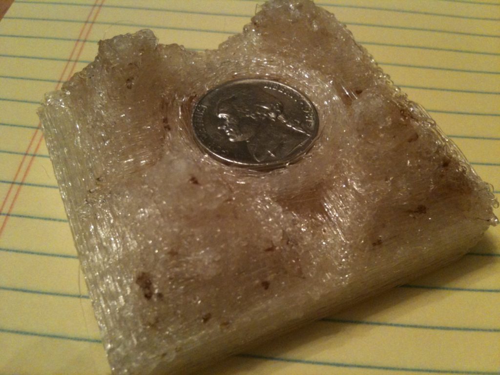
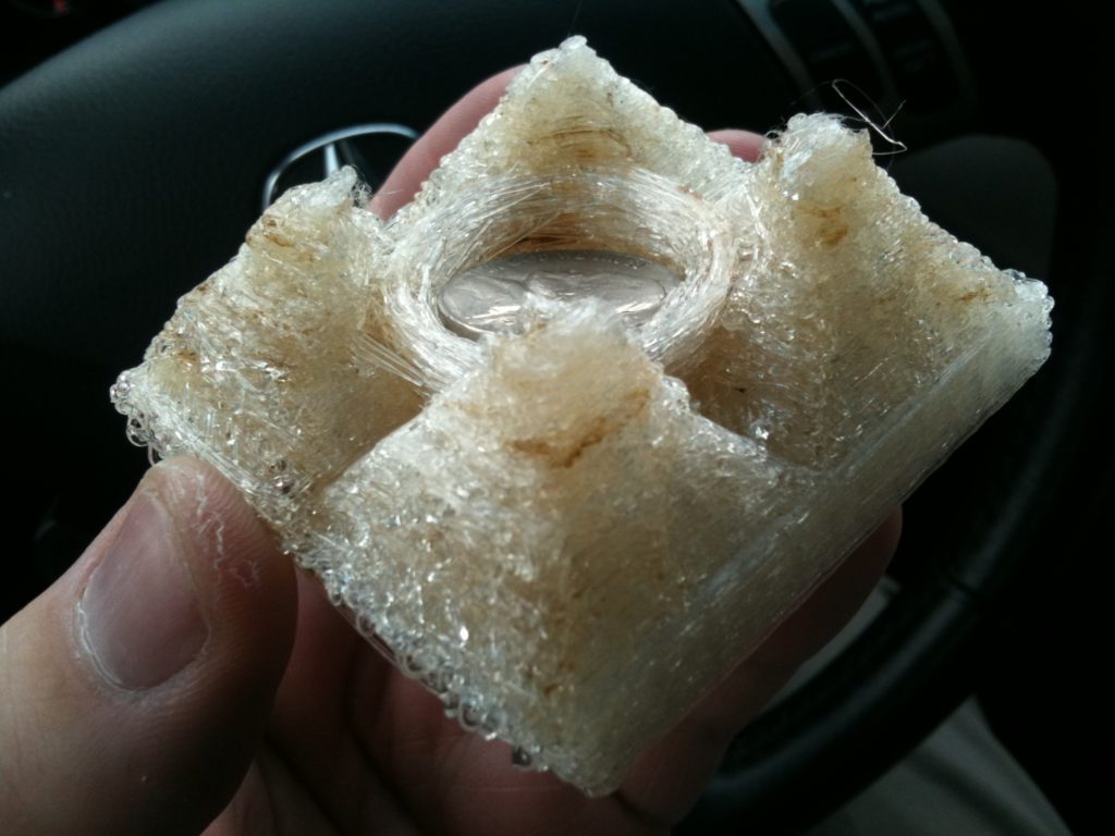
Ok. Around one year ago, wanting to experiment with using Google Sketchup for creating things to print on a RepRap (vs just buildings for Google Earth), I created a test object. I don’t think that at this point I really had any idea what the “resolution” of Makerbots or RepRaps were yet, so I didn’t expect it to come out great.

We have Coke machines at work that you have to pay for (agh!), so there’s always a need to have coins at work. For some reason, while doodling out what this test piece would look like, I made sure it’d have a cylinder in the middle just the right size to hold nickels.

Here’s the object I designed back then (that I hadn’t shown to too many people for a long time):

The circles were pulled out a bit, and the inside bottom part of the triangles was pushed in. I didn’t know if these were enough to cause overhang problems etc, but I did them anyway.

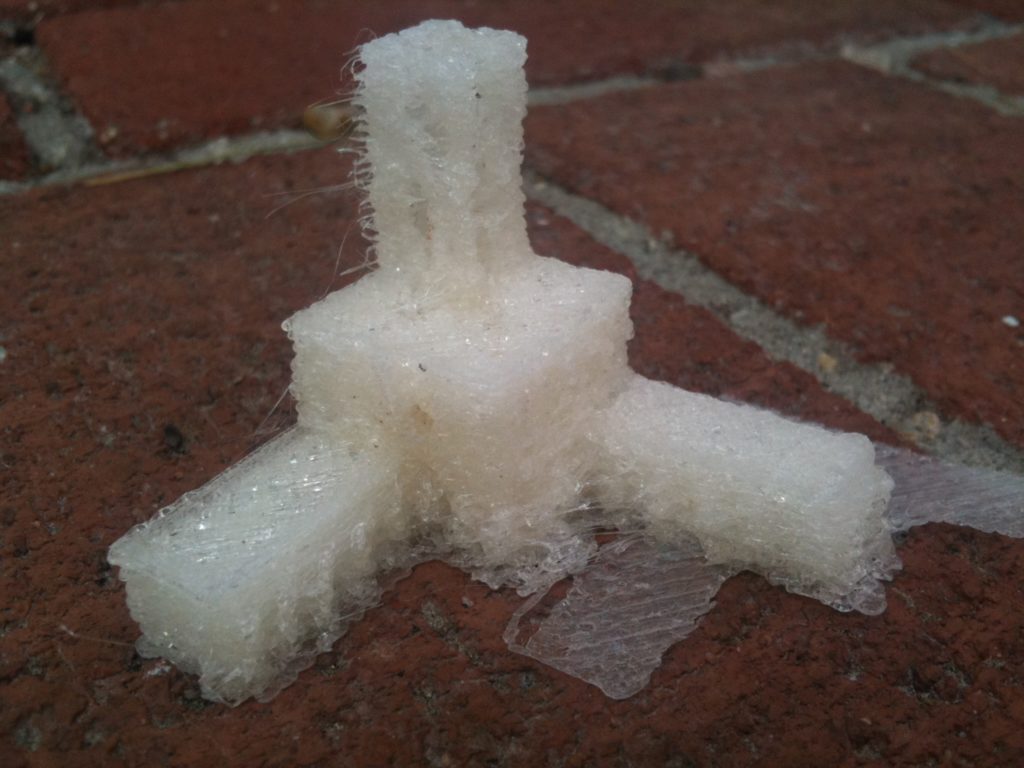
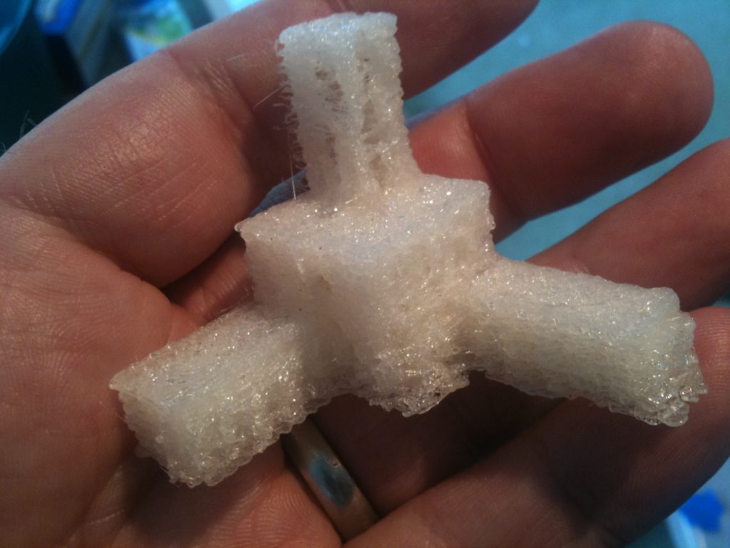
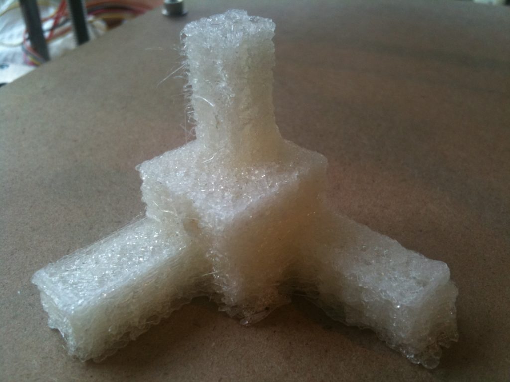
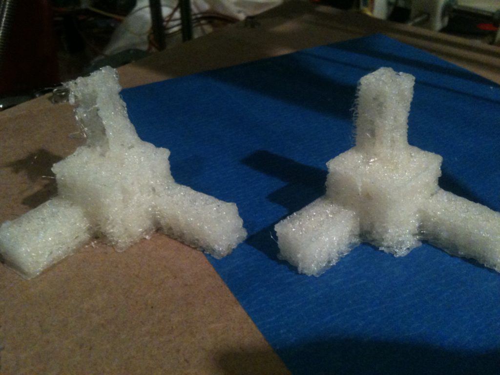
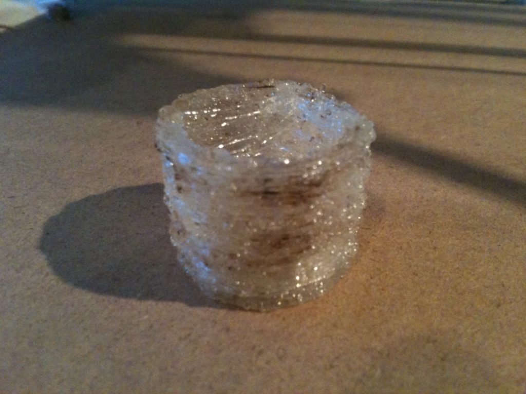
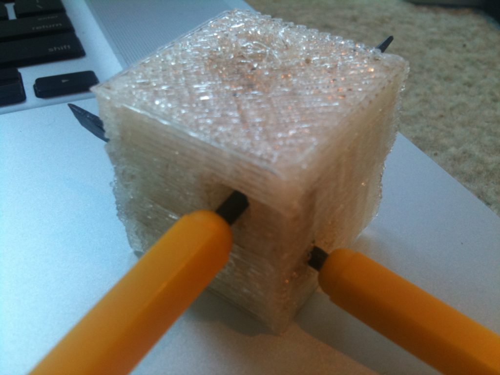
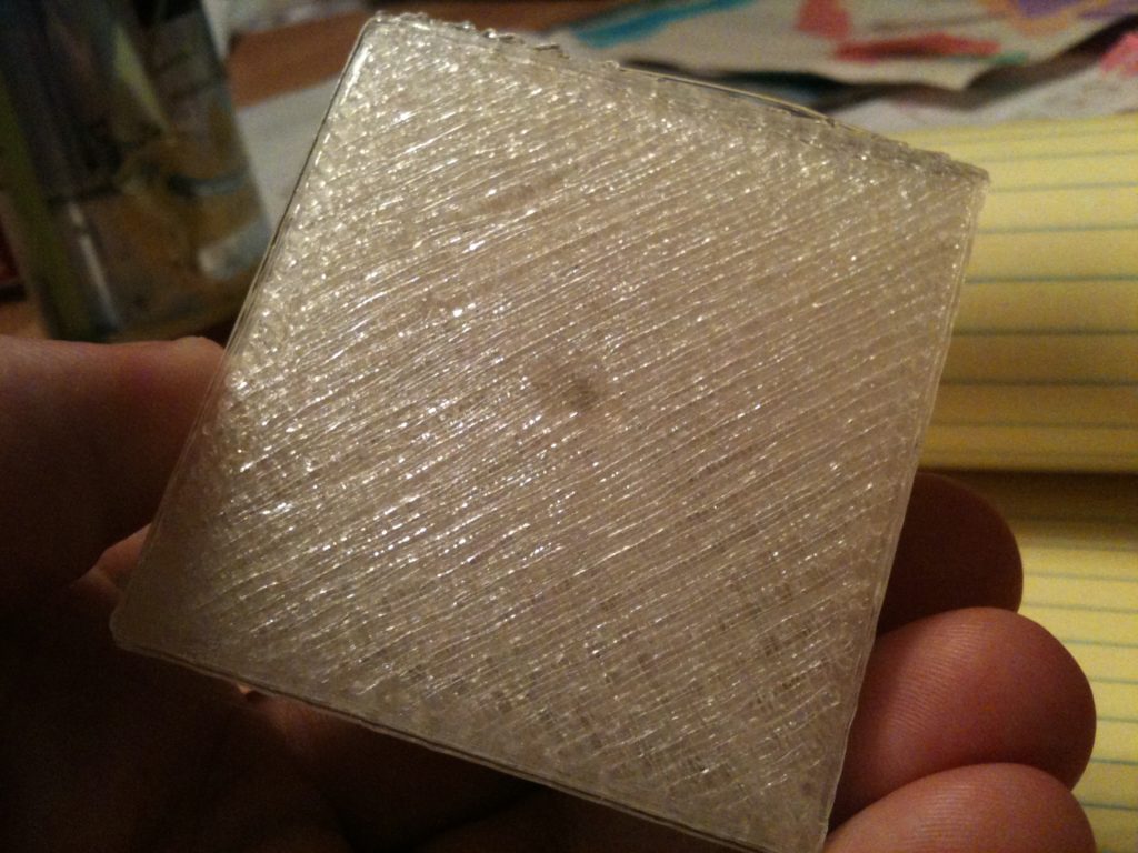
Well, I finally tried printing this. It didn’t turn out that bad for a first attempt.

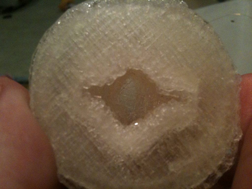
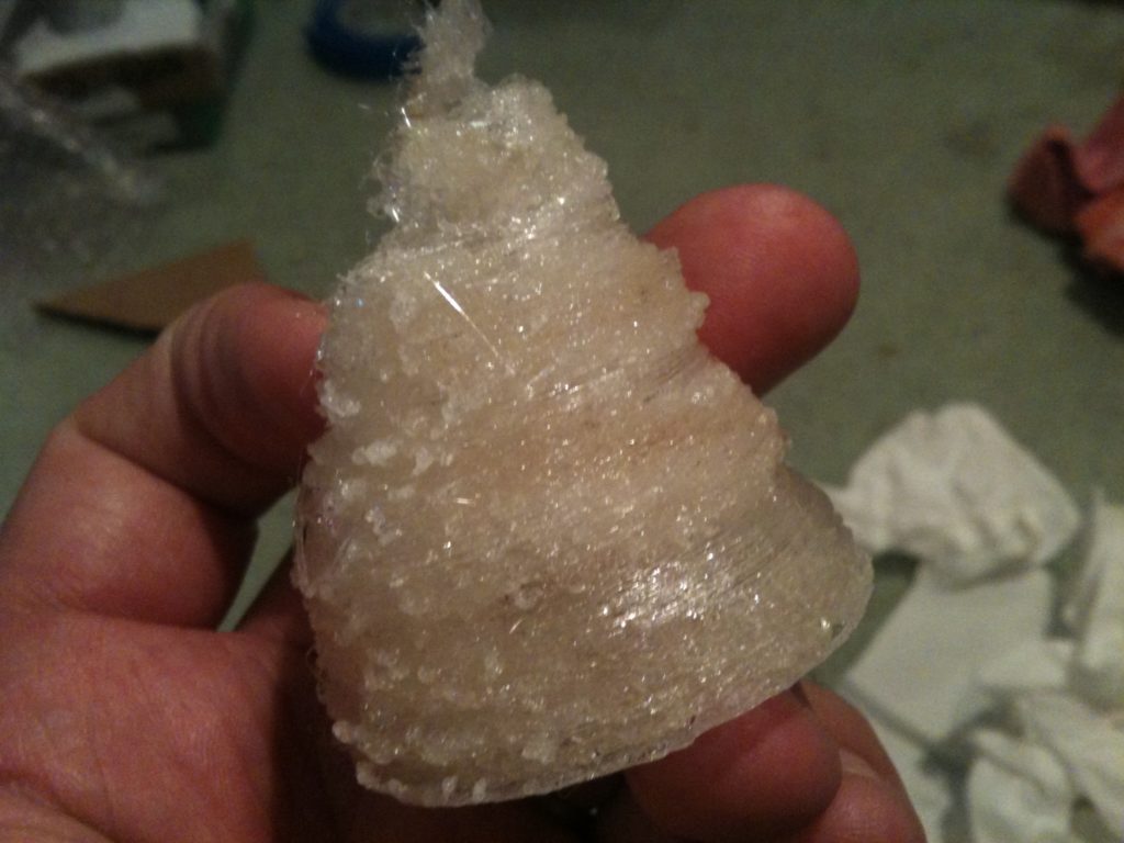
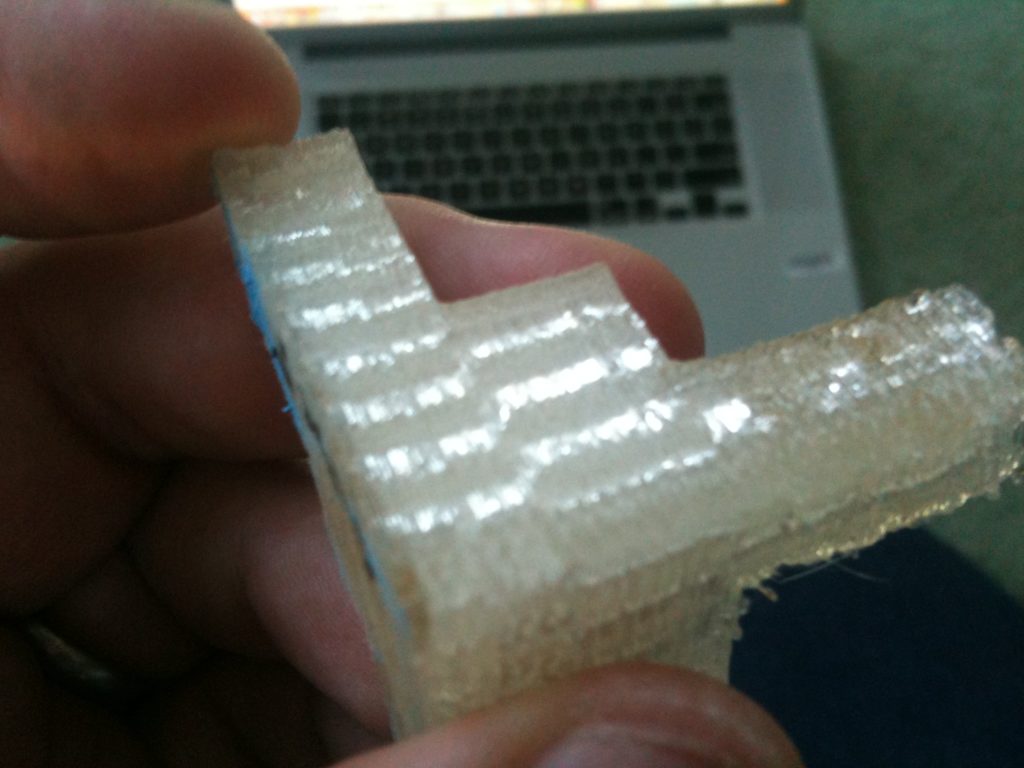
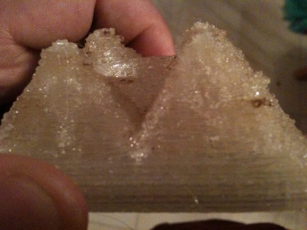
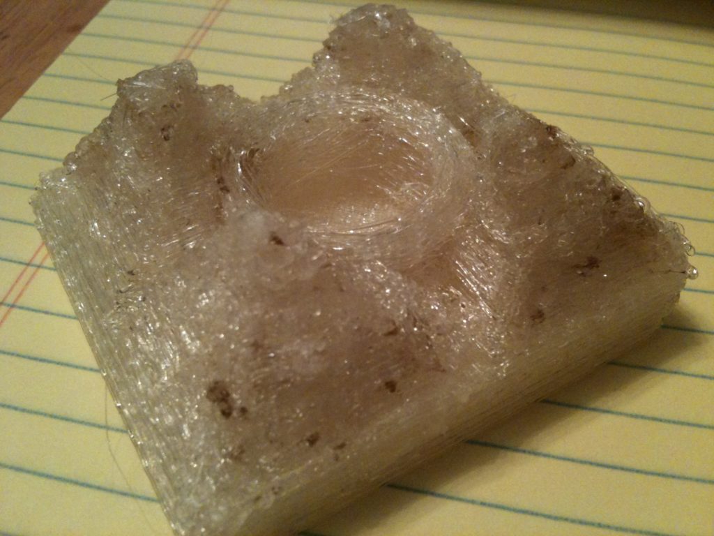
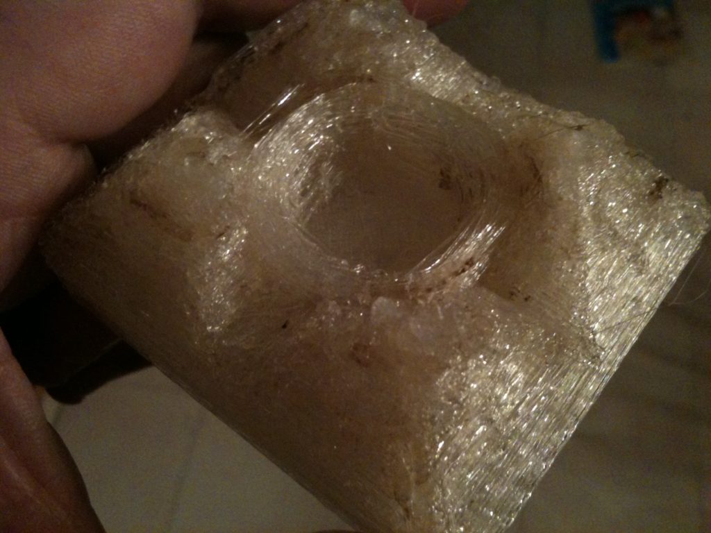
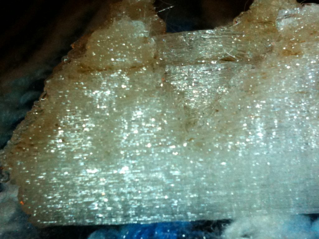
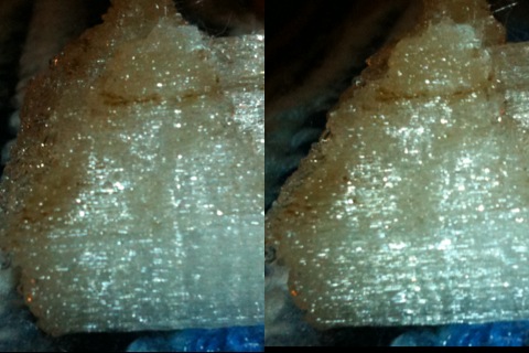
If you look really closely at the side of one of the pyramid-like points you can make out the hint of the raised circle and recessed bottom parts from the original image. Here’s a picture that kind of shows it, then a 3D cross-eye image that tries to show it too.

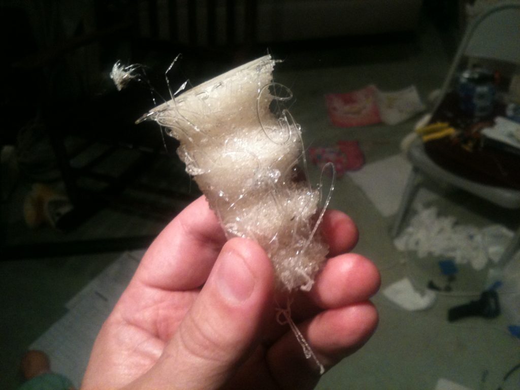
And one last picture of it in daylight that looks pretty bad (you can see hints of the problems I’m still having with my x-axis with the loops on the bottom left):

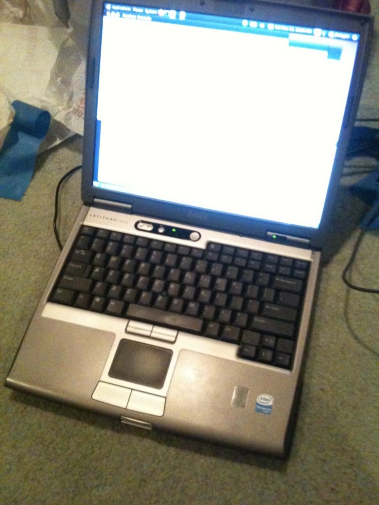
Next up: my RepRap Laptop. Wanting a laptop dedicated entirely to my RepRap, I purchased a Dell Latitude D610 for $179. When it finally arrived I installed Ubuntu 10.04 (10.10 is out but 10.04 is an LTS version).

The first thing I wanted to do was organize my work. Initially I had almost no organization for files I was printing. I was working from a virtual machine dedicated for RepRap work, so in that sense all of my files were in the same place, but they were all just plopped down in my home directory.

I wanted organization, structure, history, and process. So I created a Mercurial repository to hold all of the things I was designing, all of the things I wanted to print, and all of the things I had printed. (Mercurial is a distributed source code control system, much like git. Currently I have only the slightest bias towards Mercurial (hg) over git, but I’m still pretty close to being on the fence between the two.)

I won’t bore you with too much detail, but among other things my repository now contains three main directories at the top: thingstodesign, thingstoprint, and printedthings.

In thingstodesign, I hold projects of my own I’ve started (each has its own directory), where I can keep initial sketches, an idea.txt, and whatever else is relevant. This is one step further along than just being in my thingstoreprap list on my phone.

The next directory, thingstoprint, holds projects of my own (that used to be in thingstodesign) that are ready to move on, as well as external objects I want to print (basically things downloaded from thingiverse or some other 3D site). For things that used to be in thingstodesign, the entire subdirectory is actually moved into thingstoprint. (Remember this is all under source control, so moving things around still feels solid). No lone files – every project (even downloaded) gets its own directory.

There’s a very specific process for thingstoprint projects. They each have subdirectories beneath them named try01, try02, try03, etc. Those directories contain generated gcode, and the reprap.properties file associated with that.

Once an object from thingstoprint is considered “finished”, it’s moved to printedthings. Now that something has moved from thingstoprint to printedthings, an additional subdirectory is created alongside its tryXX directories, called “workingprint”. The contents of that are pretty much a copy of the most recent tryXX directory.

Having this process in place made things much easier. I started moving all of the things from my old RepRap virtual machine into the new repository, which I pushed to my home Linux server, which then is pulled down into the RepRap laptop. I started adding things from thingiverse that I’d wanted to print (and that I believed might print despite my x-axis problem, which currently prevents me from printing complicated things like gears). One less home directory to worry about – now everything is safe in my distributed repo.

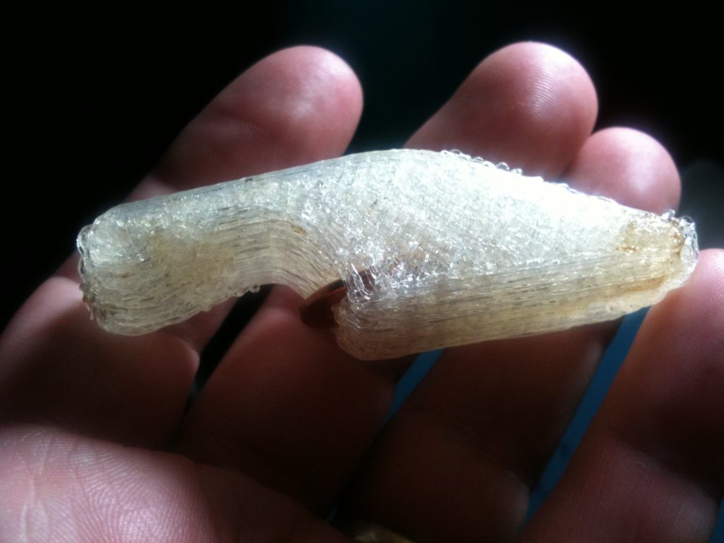
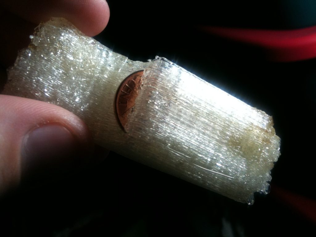
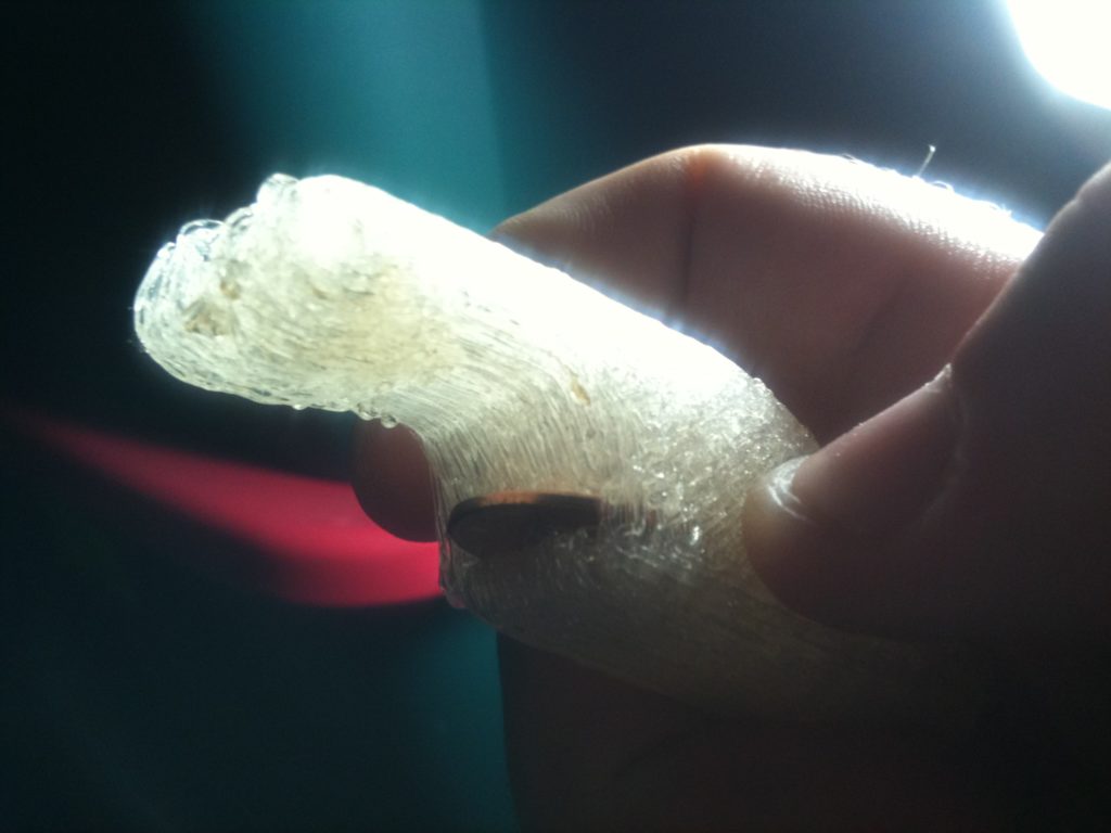
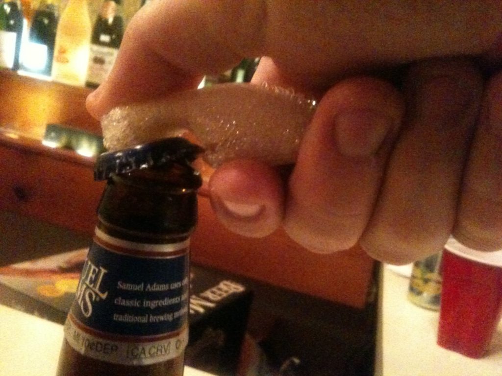
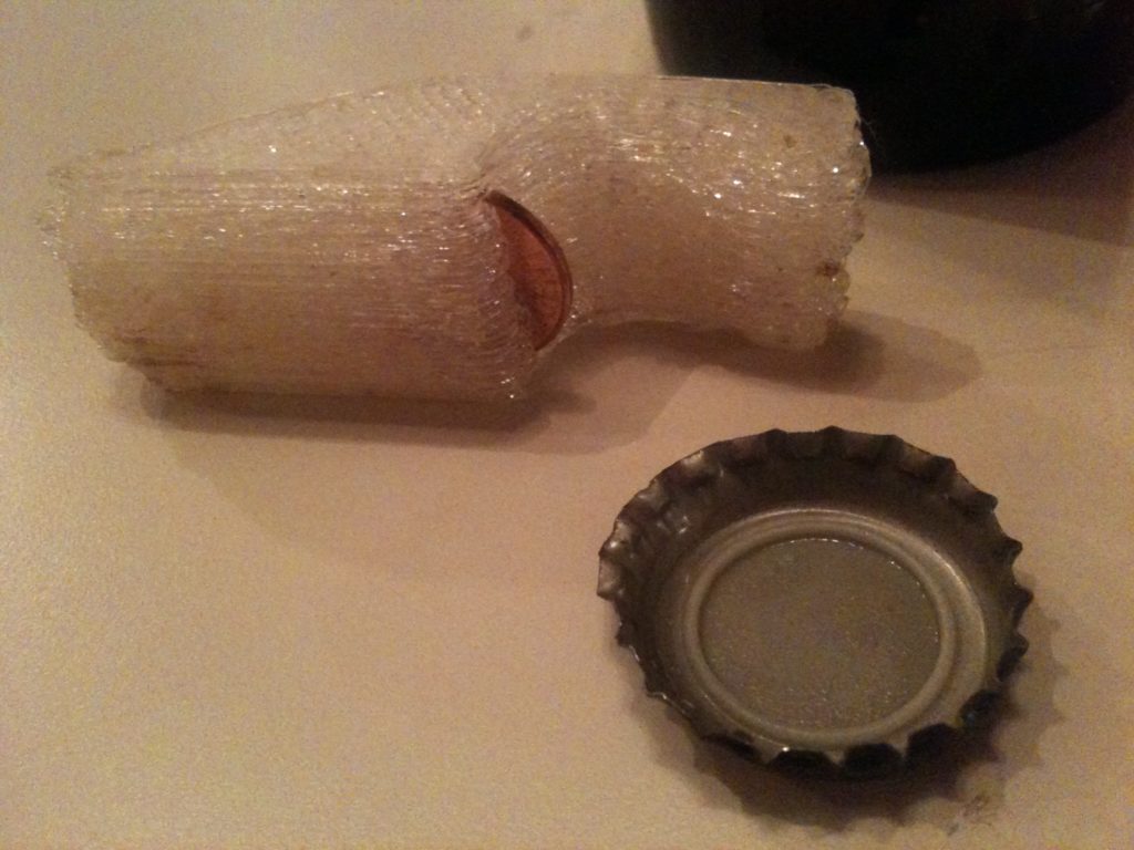
One of the things I’d been meaning to get around to printing (to help with my elevator speech) was the coin-based bottle opener. Although I downloaded that into thingstoprint, I also downloaded a derivative part with chamfered edges and a keychain hole that I decided to print instead.

You put the penny in so the metal of the bottlecap doesn’t dig through the plastic.

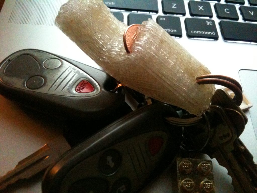
Here it is on my keychain (it wasn’t easy to get on!):

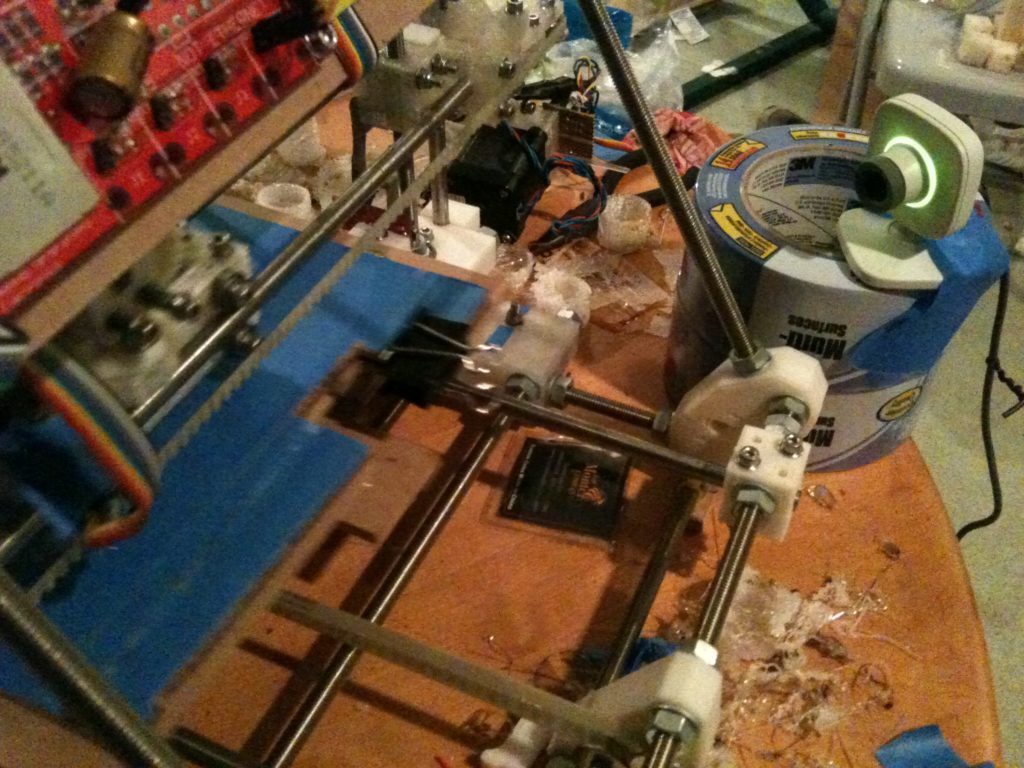
While the bottle opener was printing in the sunroom (the room near our still-to-be-closed pool, which becomes very cold), I thought back to when I’d propped up my Rovio remote webcam in front of the Makerbot eleven months ago. Seeing prints remotely was nice, but I had to artificially keep the Rovio from driving off the table. I wanted a better solution, and immediately thought about the old USB XBox Live Vision camera I had lying around (they’re around $40 new). One Google search later and I found a quick description of how to get it up and running on Ubuntu with almost no effort, streaming video to a remote web browser.

I can access either static screenshots or streaming video from a web browser. Here’s a view saved from my computer:

..and here’s one saved on my iPhone the next morning.

Portrait view from my iPhone

One of the first things that I read about people printing on their RepRap (other than other RepRaps) was a coat hook. I decided it was finally time to print one. Before taking Alicia and Cara to their gym class in the morning, I started the coat hook print. Here’s how I knew it had completed successfully – an image seen and saved on my iPhone (landscape mode this time):

The build is done!

When we got home we ran in to see the resulting print:

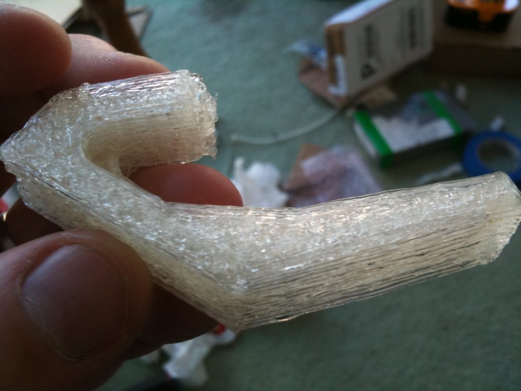
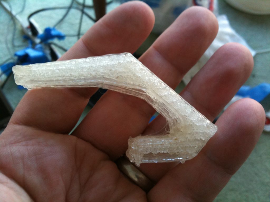
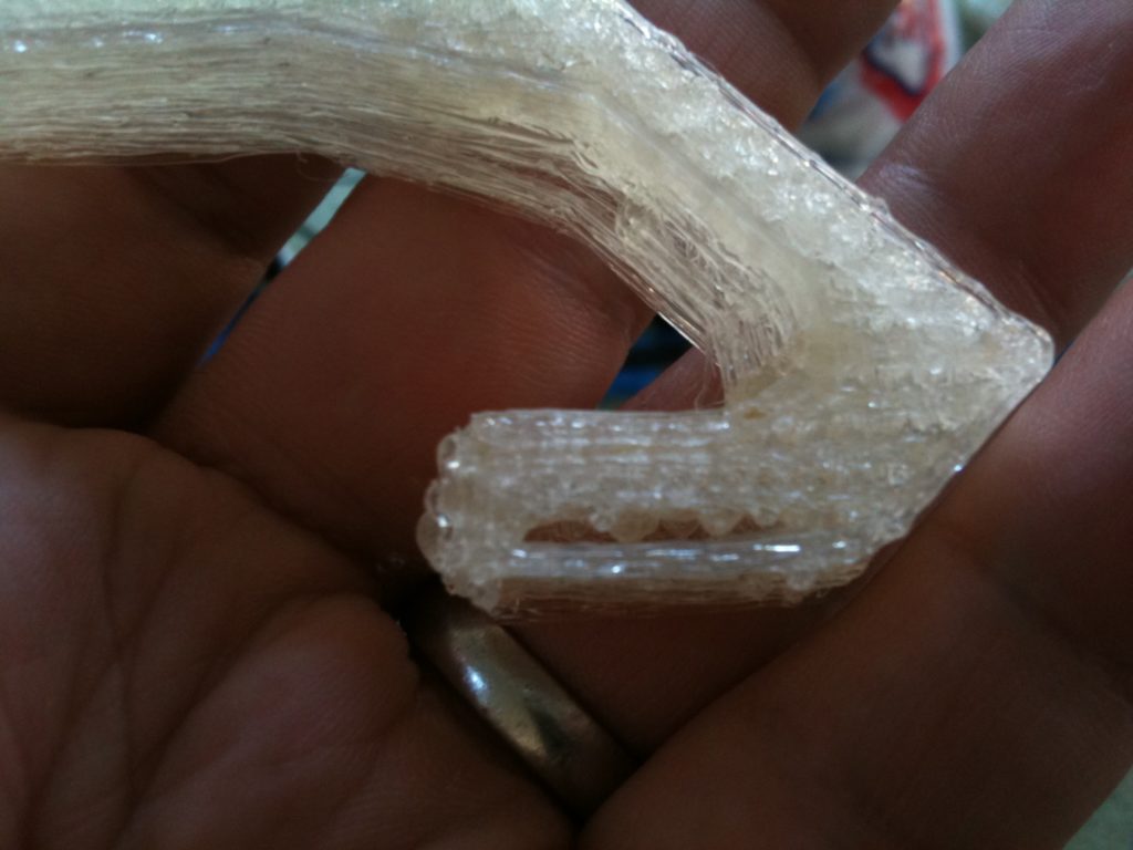
If you look closely you can see that even on a piece as simple as this, I’m still having problems.

And then of course, another disaster. It didn’t start out as a disaster, just as a strange problem with the extruder stopping occasionally.

Maybe there was a jam inside the barrel, I don’t know. Anyway, then this happened:

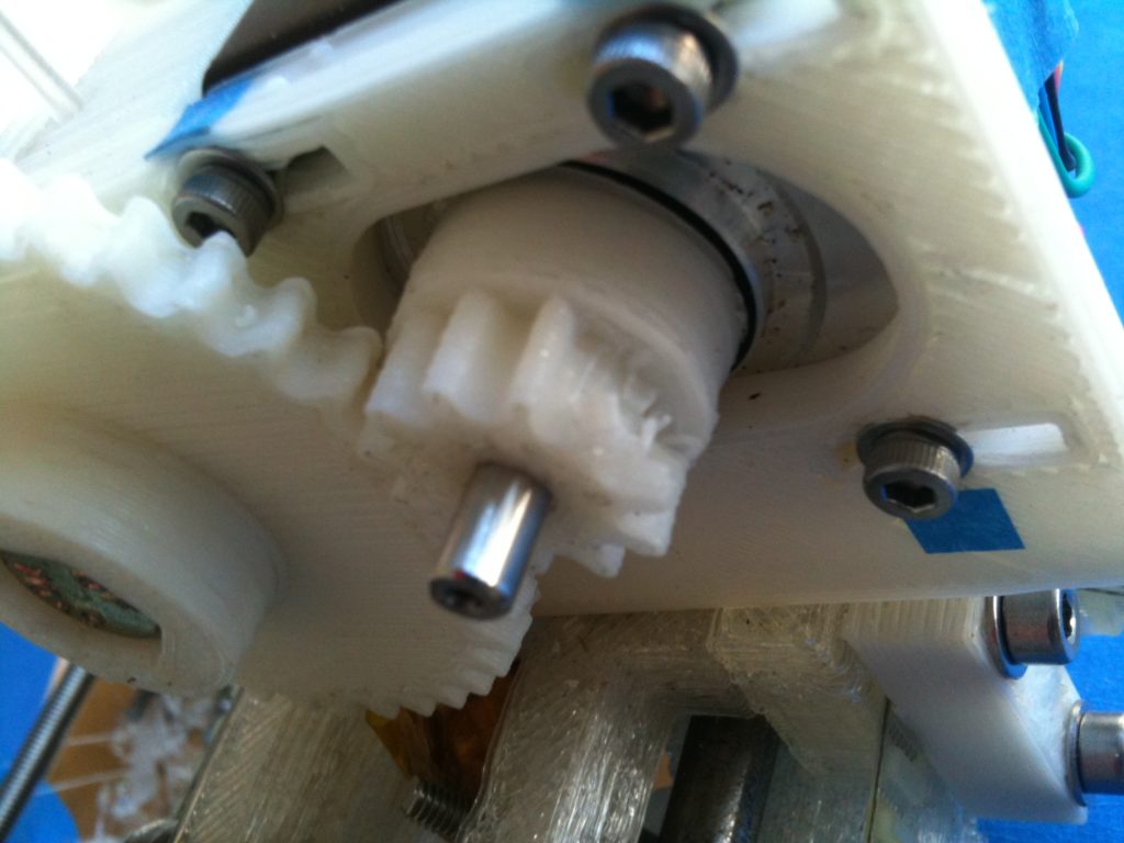
I’d stripped the gear. 🙁

I bought two small and two large gears printed Wade’s gears in the mail to replace this (thanks Tony), which should be here in a few days. That’s why I had time to write this up for you to read. 🙂

With respect to the x-axis problem, there are a bunch of things I can try. It feels like backlash – frequent left-right actions cause some accumulating error (that doesn’t happen with the y-axis). I can tighten the belt, grease the rods with silicone grease, etc. But I may remove the belt and just ensure that the carriage smoothly moves along the axis. I don’t think the screw for the extruder mount is going too low into the bar but I’ll check that too. Since I have a few of the nophead pulleys from Neil’s original part shipment, I could try putting that on the X-axis stepper instead of the mcmaster pulley I’m using (meaning I’d have to do some calibration again since it’s 8-toothed while the mcmaster pulley is 10-toothed), but then again there’s a new 9-toothed printed pulley being talked about (but I think that needs a new end bracket..).

Nah, if the Y axis is able to move with a mcmaster pulley, X should be able to also. Maybe it’s the weight of the stepper motor pushing down on the bars, or its inertia resisting left-right motion? Maybe one of the bearings is clogged up and not turning smoothly? Maybe one of the bolts holding the carriage together is too tight? Did I ever file down that X-axis stepper shaft? Or then again it could all just be the belt not being tight enough.

I’m just happy that I’m down to a few identifiable problems between now and me being able to print functional Mendel parts. It’d just have been nice to be able to do that before wearing out one of my extruder gears. 🙂

One Year

Sunday, October 31st, 2010

On October 29th, 2009 (one year and two days ago), I threw my hat over the wall and spent $180.00 on electronics for my Mendel RepRap.

This has easily been the coolest thing I’ve ever built. It’s been unbelievable fun, and I encourage everyone who’s ever even thought about building one to go for it.

Using a MakerBot (that I and a friend Chris built, on loan from work) as a RepStrap, I printed all of the pieces for my Mendel, except for a few. I was helped out over time by mccoyn, spacexula, and work, who provided a handful of parts after I lost possession of the RepStrap.

On July 10th, 2010, I had my first extrusion from my own Mendel RepRap.

To anyone thinking “wow, nine months – that’s a huge amount of time”, don’t be scared off. While the first stage took a long time of many concentrated hours printing all of the pieces for my Mendel on the RepStrap (before heated beds were plentiful, and suffering with the unreliable Makerbot MK4 extruder), the time AFTER that (actually building the Mendel and doing calibration) was far more spaced out over time..

Even so, this has been a great hobby to fill out the last year, and I’m more than happy with my rate of progress.

I’ve printed several watertight minimugs, but no alcohol-tight minimugs. I’m not sure if the particular beverage I’m using is reacting with the plastic somehow, or maybe it’s because alcohol-tight is finer than simply water-tight (which I read somewhere on the internet, so it must be true).

I’ve printed a bunch of calibration objects, then used them to calibrate my machine. It now prints far better, but still no alcohol-tight minimugs. The one takeaway that prospective RepRap builders should learn from this post is this: the tradition of having a minimug be the first thing that you print (and toast with) should take a back seat to printing several calibration objects first.

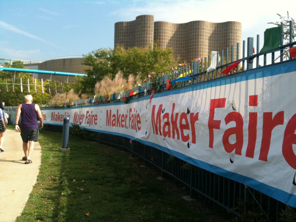
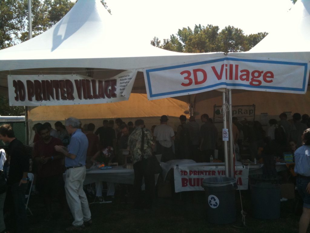
Ok, lots of talk, no pictures or video so far, and it’s been at least a month since my last post. Here we go. First, I went to Maker Faire NY 2010, along with my Dad (Larry), my brother (Jon), and my baby nephew Blake. It was VERY cool meeting several people who had also built their own RepRaps.. There were Mendels, an incomplete Huxley, a RapMan, lots of MakerBots, and the Fab@Home guys had stuff there too. All very cool.
My brother Jon and my dad Larry
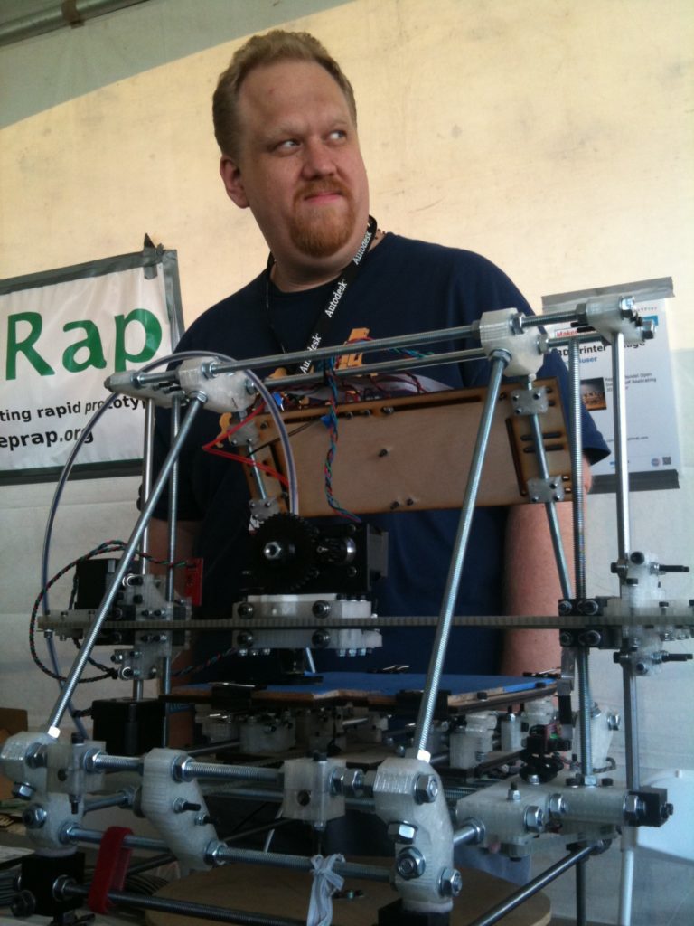
One of the first things I did was to find Tony Buser and see his working Mendel. His Mendel looks awesome, and it works. 🙂
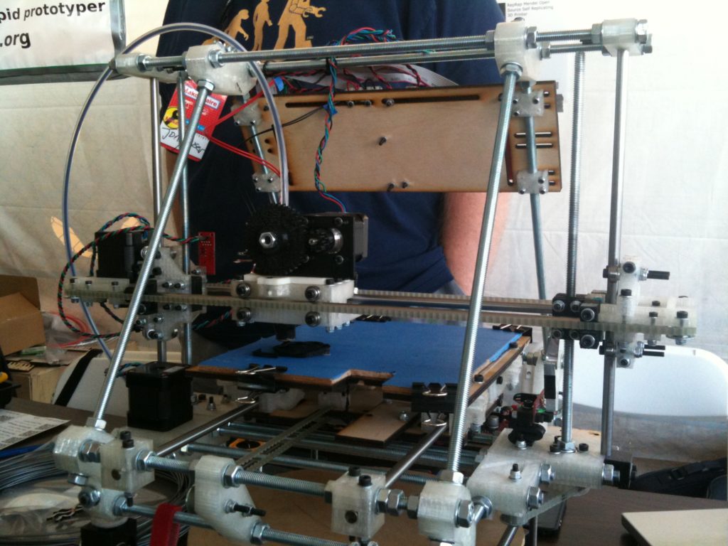
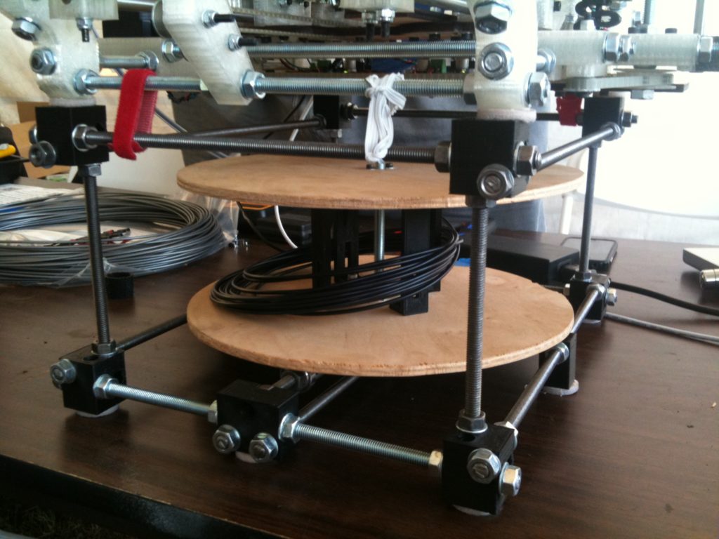
Here’s his filament spindle, which I was eager to see in person:
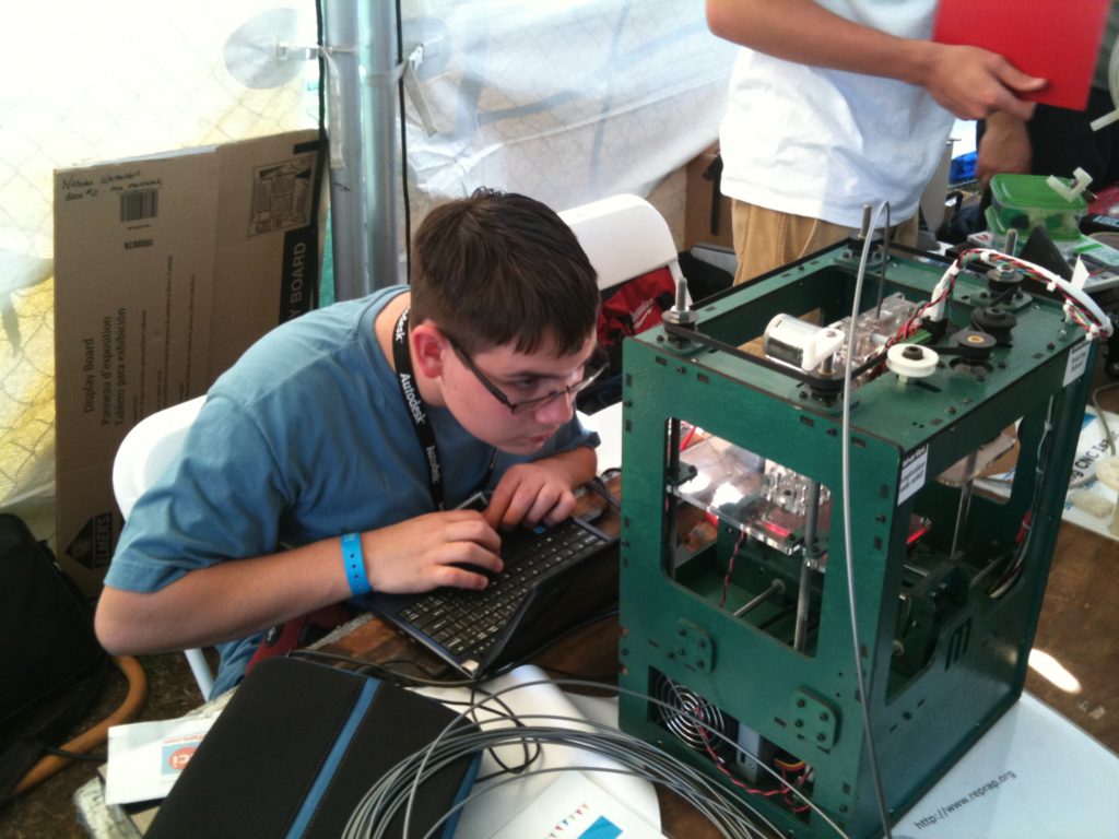
Nicholas Wattendorf was there with his dad Bruce.. They’re in the New England RepRap Group with me, but I hadn’t met them in person yet until this event. Here’s Nicholas with their green Makerbot, doing that stare-into-the-printer that we all do so often:
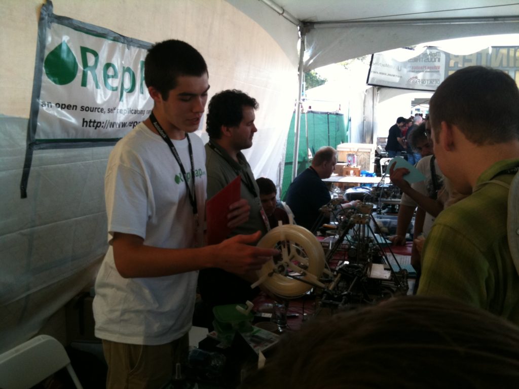
If I remember right, this was Ethan Dicks in the foreground (I believe he was the one with the first Adrian’s Geared Extruder that I’ve seen in person vs online), and Lambert Andrus from Techzone was behind him:
Here are one of Andrew Plumb (clothbot) building a MakerBot during the show (with his hand on the Makerbot), and Rick Pollack (makergear.com) in the orange shirt in the back right.
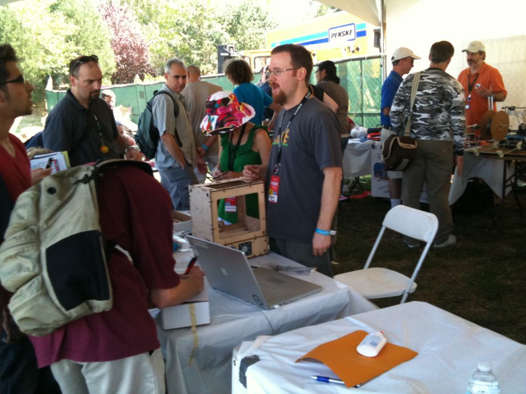
I also spent a bunch of time talking to Andy Smith, Tony’s wife Amy, John Abella and his dad, and others whose names I can’t remember, but I don’t have any pictures of them.

The MakerBot booth had a bunch of printed demos out for people to see:
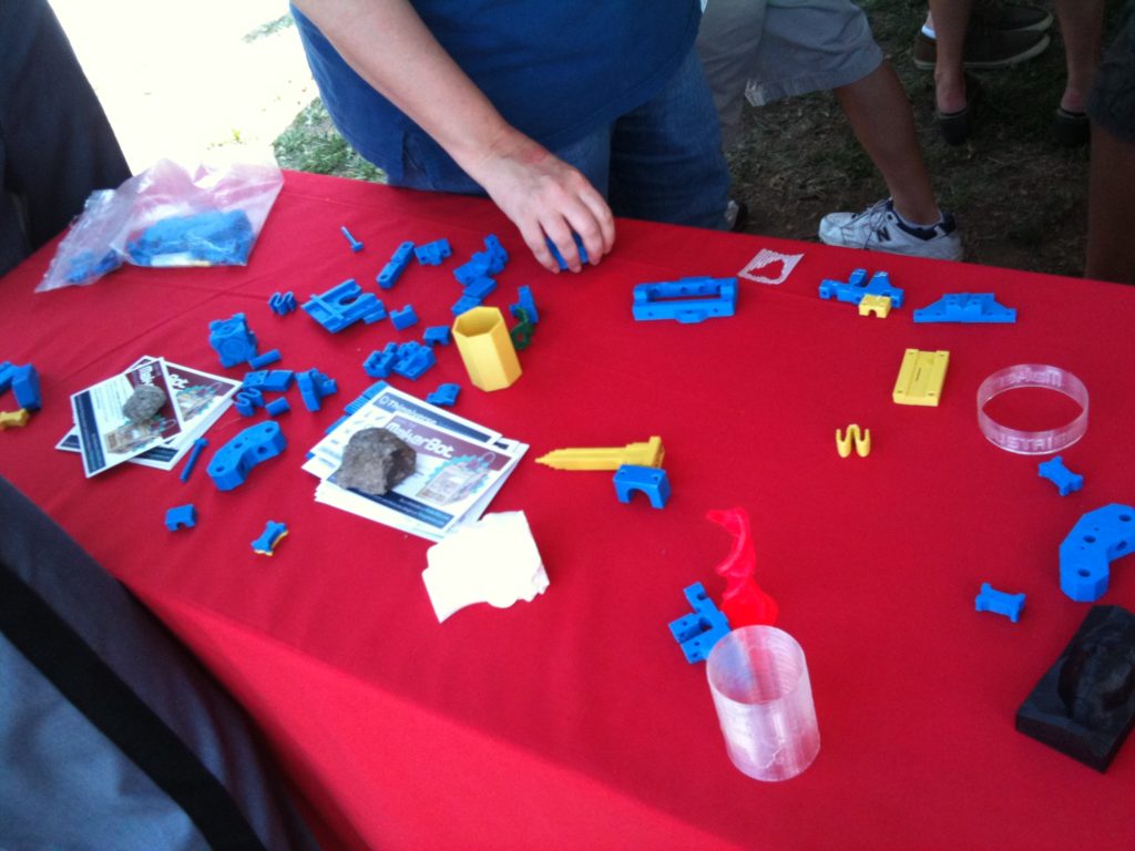
I was able to meet Bre and Zach too – I met Bre when he was showing off the Thing-o-matic, and met Zach on the way into the faire.

Oh yeah, the Fab@Home guys were there too, and they were printing turtles out of spray cheese:
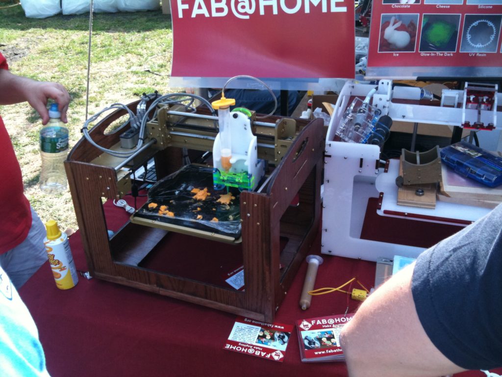
After the first night of Makerfaire I wanted to run home and calibrate my machine, but seeing as how we were in Brooklyn NY and I live in Methuen MA, I’d have to wait. We went back for a second day of Makerfaire (no pics, my iPhone was full), then came home. Soon after, I started back in with my RepRap.

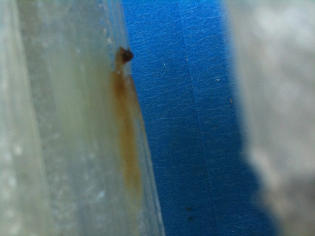
One of the problems that my most-recent-at-the-time heater barrel had been giving me was that it would output smoke. I wasn’t exactly advertising this fact, but I kept a close eye on it, and the first thing I had to do was fix that. At first I feared the smoke had something to do with the heater barrel being too close to my X-carriage (made out of PLA):
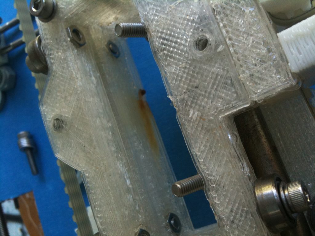
I noticed the hole for the PTFE insulator was off center:
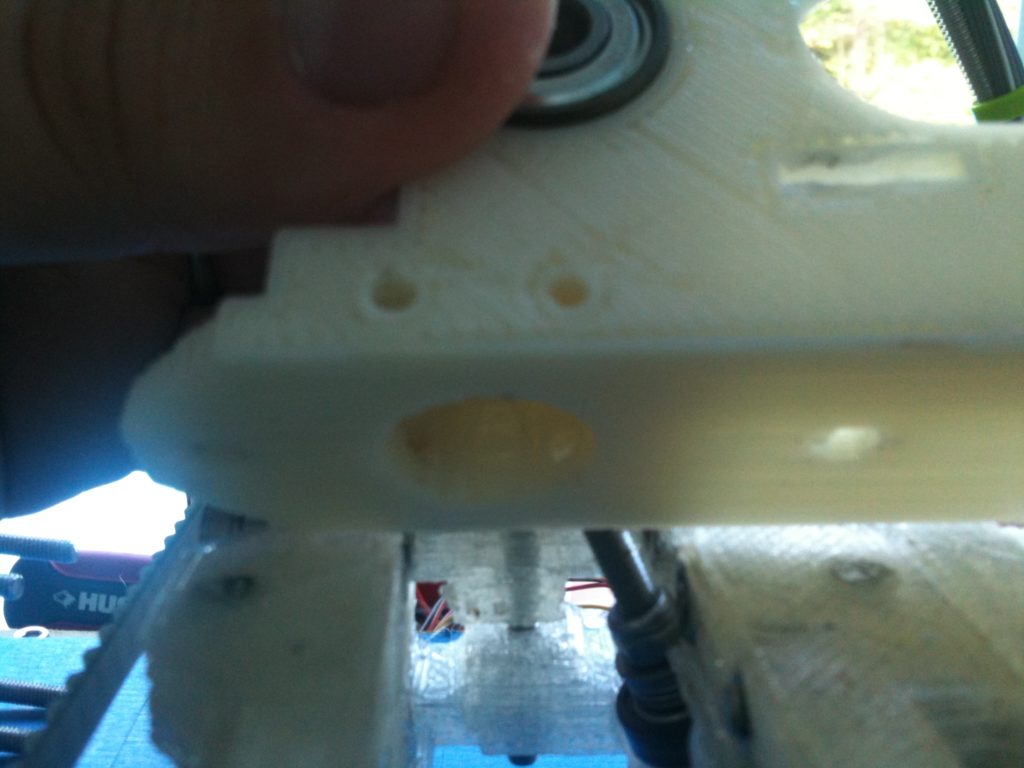
..as did others. Originally I thought it was only in the shortened version of Wade’s Extruder (the one made smaller to fit on a Makerbot), but apparently it’s in all versions. Tony Buser made a sideways mount that I’ve tried printing twice that addresses this problem.

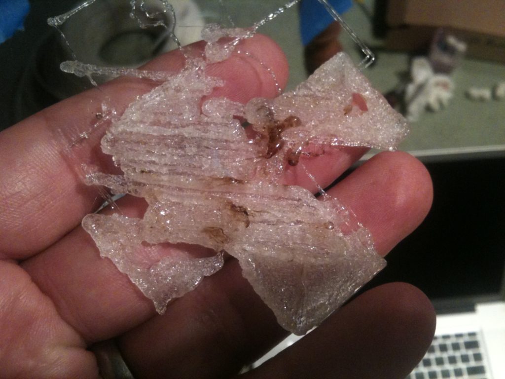
The first attempt a while back was horrible (had to abort after a few layers):
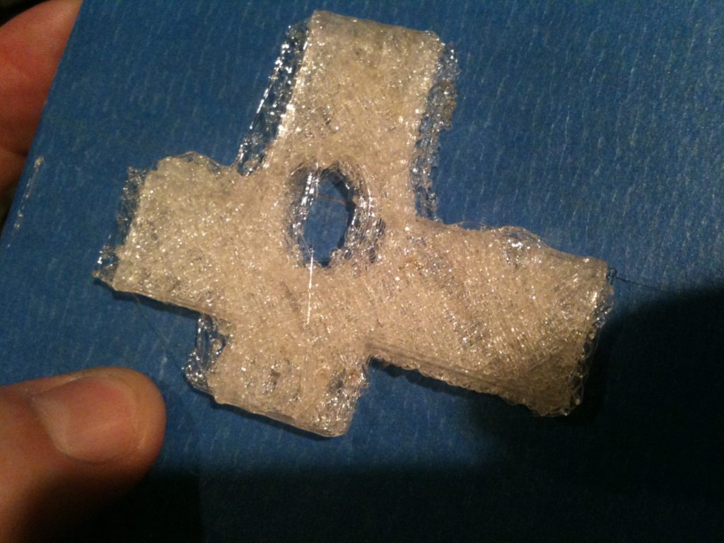
While my most recent attempt is merely ugly but might work:
But I’m getting waaaay ahead of myself. Ok, back to the smoke. I took out the PTFE (which I could do, since it’s not glued into the extruder), and tried turning up the heat just a little. This produced enough smoke to convince me that the smoke had nothing to do with my x-carriage – it was instead just a poorly wrapped bit of nichrome wire (and a thermistor that wasn’t in good contact with the nozzle).
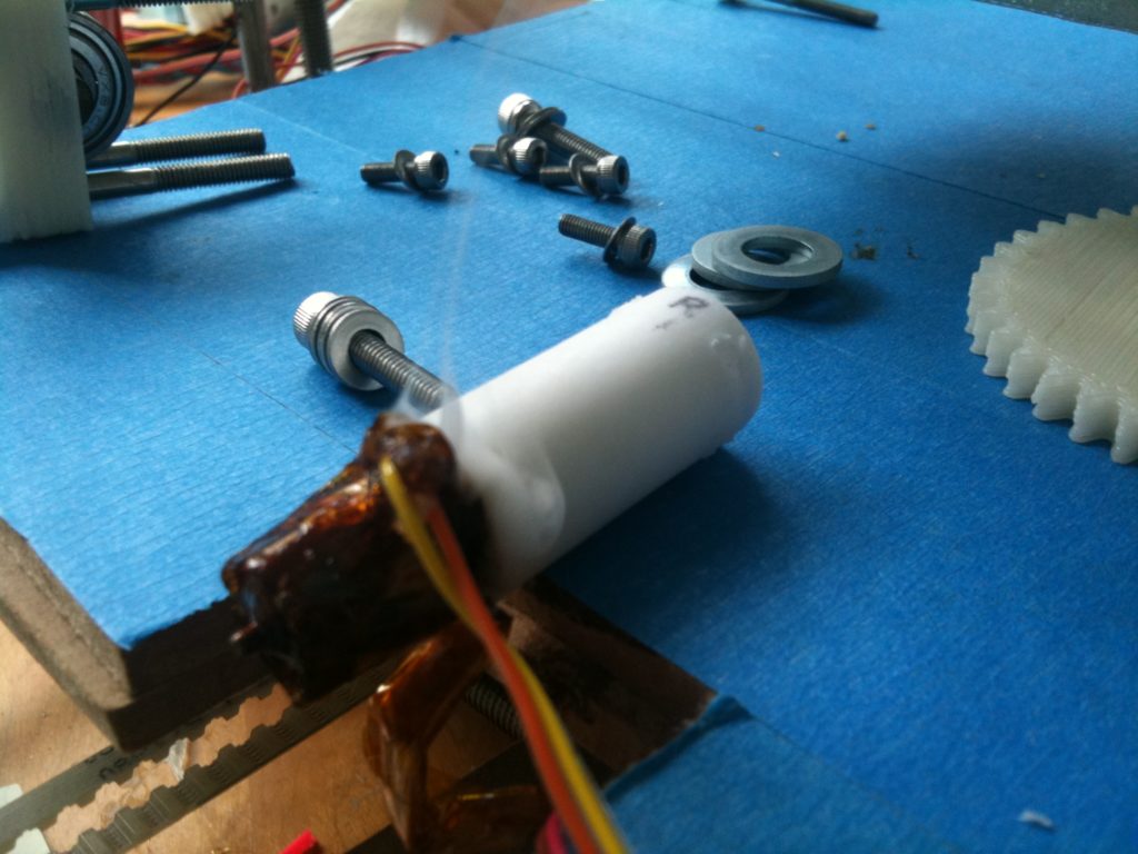
So I dismantled the heater barrel and went to start again. For some reason I tried to get the nozzle off of the head of the barrel (can’t remember why I tried that), and I ended up breaking the barrel. It was easy enough to make another, but I didn’t have a spare nozzle handy. (As it turns out, I actually had TWO handy.. I had another MakerBot nozzle I’d bought as a backup backup spare, and Rick Pollack had given me a BigHead nozzle at Makerfaire, but I didn’t remember either of these at the time).

Lacking any memory of having a nozzle available, I decided to create a barrel that was its own nozzle, like the original Mendel plans called for (and like I’d done on my first heater assembly experiment, but had never used). I’d purchased a few 0.5mm drill bits during my last mcmaster purchase, so I decided to give it a try. I went back to the recommended 32mm length, tapered off the edge first to make it pointy (but with a flat end at the end of the taper), drilled the 0.5mm hole (breaking one of the bits in a stupid accident), then drilled the barrel out. It came out rather well:
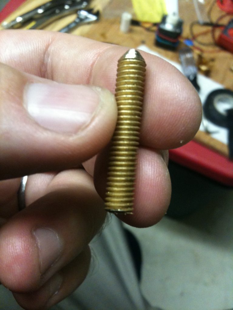
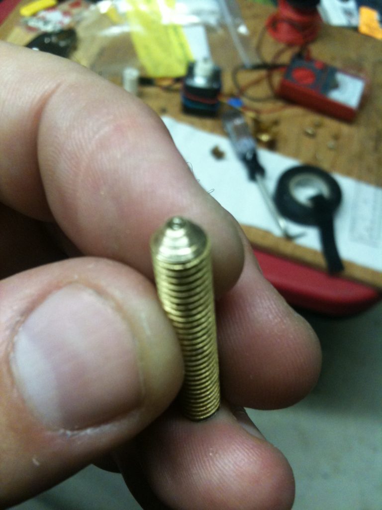
(then again I’ve only been printing PLA, so I didn’t need to maintain much heat.. maybe ABS would require more metal to keep the heat going)

While the extruder was disassembled I also was able to finally address my spring issue. The springs I bought from mcmaster were too big, and I’d been thinking of cutting them in half but I hadn’t gotten around to it, and was wondering if instead I should just shop around for better fitting springs. Tony Buser had mentioned at Makerfaire that he’d cut his and they worked great, so now I did that.
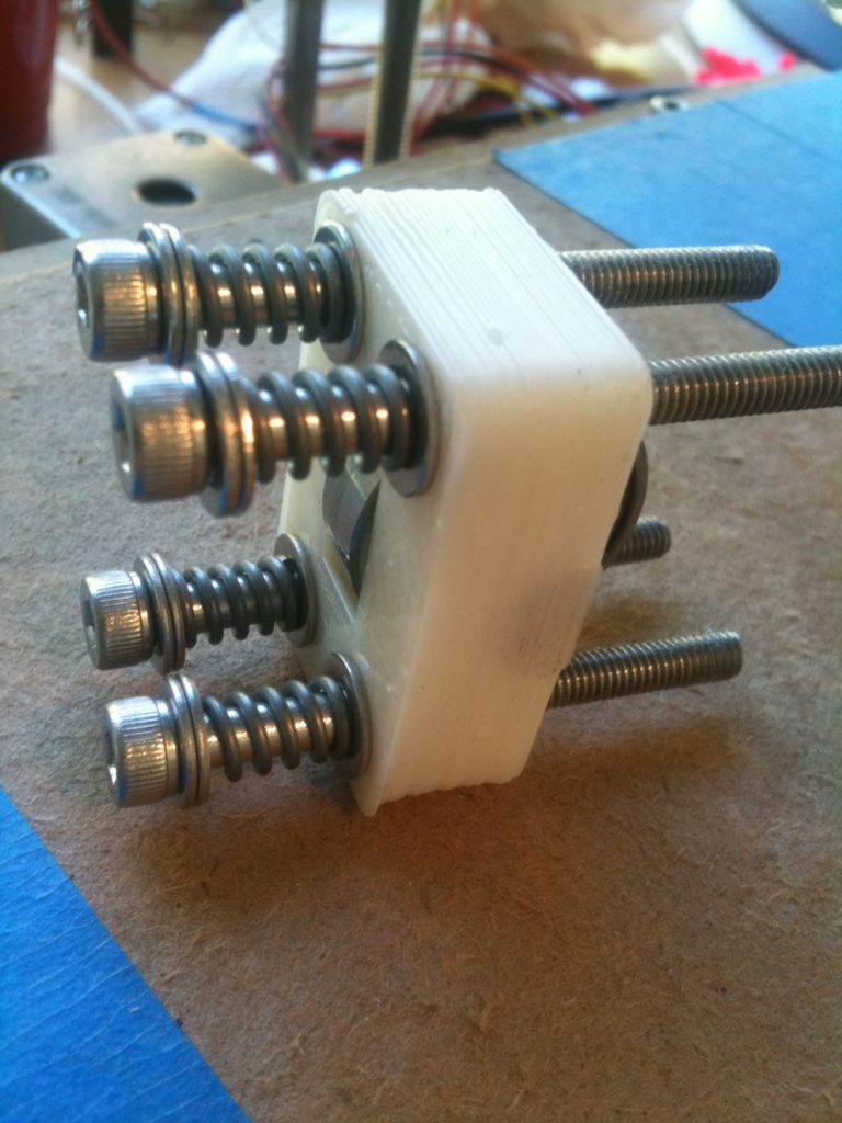
Of course, there’s something wrong with that picture (which persists on my RepRap still, and will until I take it apart again). When assembling my Wade’s extruder, I had an idea of how it was supposed to go together, and that idea contradicted what I saw in front of me. There are hex-shaped recessed areas on the motor side of the M4 holes for those four bolts. Since the BOM didn’t say anything (at the time) about hex-shaped heads, I’d bought the usual round socket cap bolts. With those round bolts, the only thing that made sense for those hex-shaped recesses was to place trapped nuts inside them. That would mean that the heads of the bolts would be on the other side of the idler bracket, as shown in the picture above.

I even went so far as to helpfully add to the wiki page for Wade’s extruder that the bolts in his picture were backwards, since at first glance it looked like another picture below it confirmed my suspicion that the picture was wrong. I’ve since removed that wiki change, since I was wrong.

What Wade really intended was for cap screws with hex heads, with the bolts backwards from what I have above. The head is trapped by the recesses, and the bolts protrude (for the inset to be slid onto). It seems that that means every time you fully remove and reassemble the idler bracket, you have to take off all of the washers and springs, but at least you don’t have to worry about a trapped nut being pushed out of its recess.

Ok.. So at first, I wasn’t having very good results printing at all (but of course, the smoke had stopped!). The problem was that my Y-axis opto endstop was malfunctioning. The prints were laughably awful.
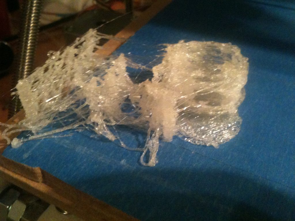
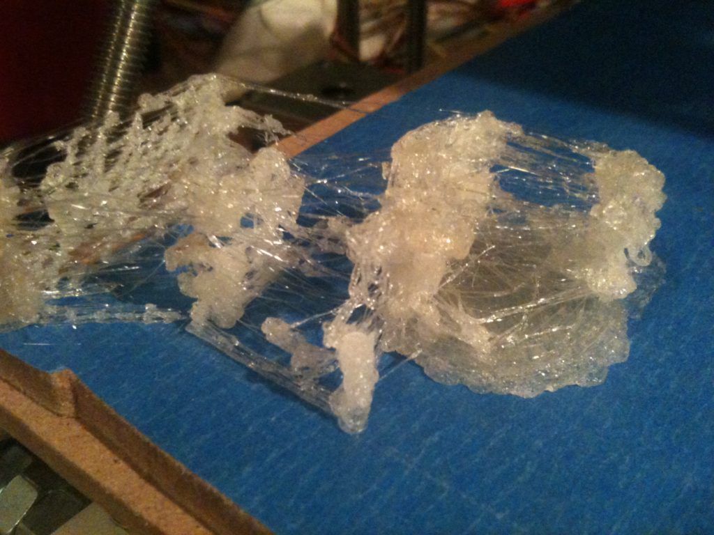
The problem ended up being that either the cable for my opto endstop is flaky, or possibly it’s the connector soldered onto my y stepper controller. My super-short-term fix was to put a twist tie around the cable, holding it down in such a way that the signal stays solid 100% of the time (I need to make a new cable). I forget where along the line I figured out that it was the cable – it was definitely after some of the pics below.

So, after printing at least 40 minimugs (33 different gcode files, but with multiple copies of some), I was getting pretty sick of printing minimugs. So I decided it was time to print a calibration object to double check my X and Y calibration (I was previously fairly certain that Z was correct).
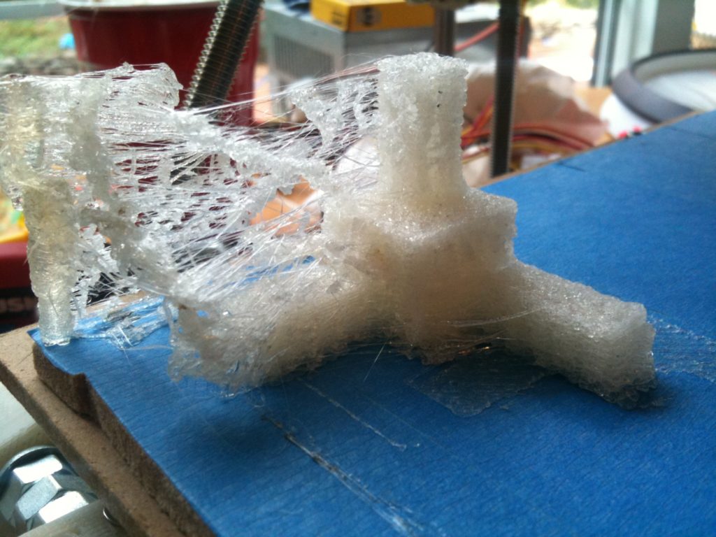
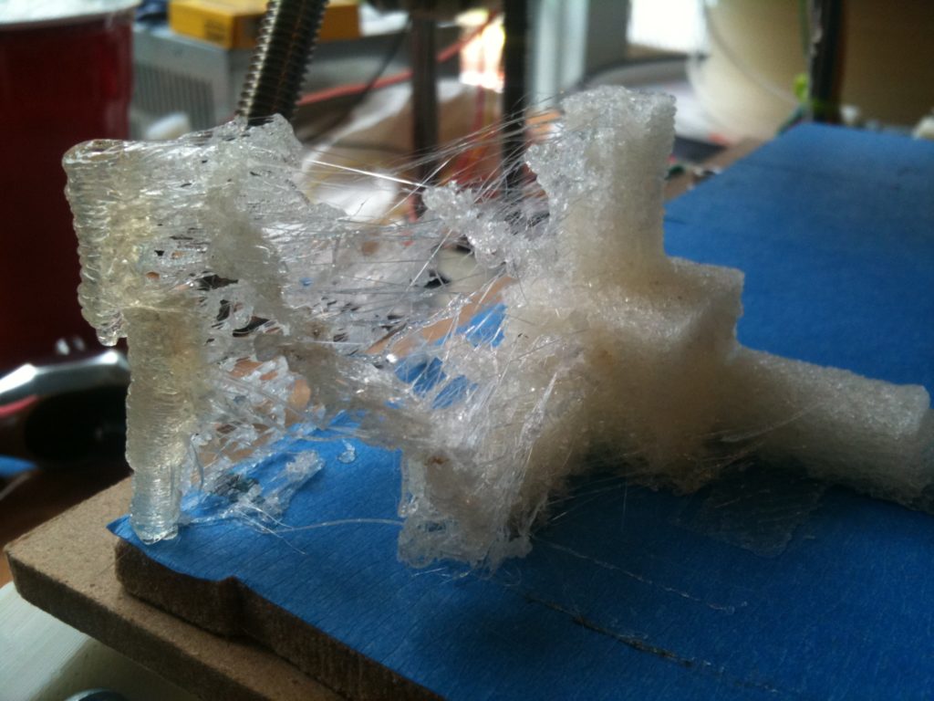
That first print was still pretty bad but it was at least slightly measurable. I printed four more of these in all, three of them before calibration, and one after.
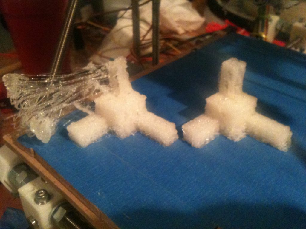
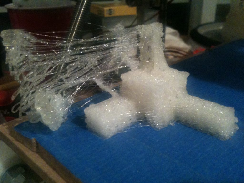
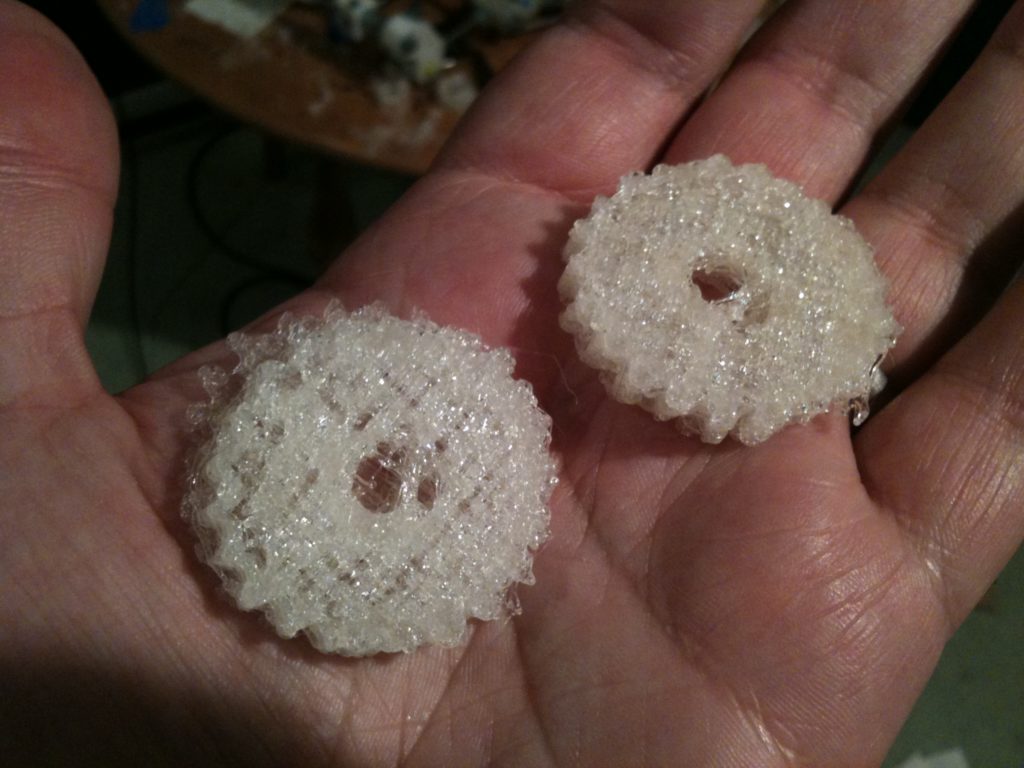
Before I got to calibration though, I found myself wanting to try printing some other things (knowing they’d probably fail), just to add some variety to this whole exercise. Here were two horrible z-driven-pulley gears, like I wear on my badge at work:
(Again, this was before calibration). Also before calibration, I printed the sad Christmas tree that I’d printed two of on the RepStrap. Those earlier versions (made in ABS) came out great. This uncalibrated version wasn’t great, but at least it looked a bit like a Christmas tree.
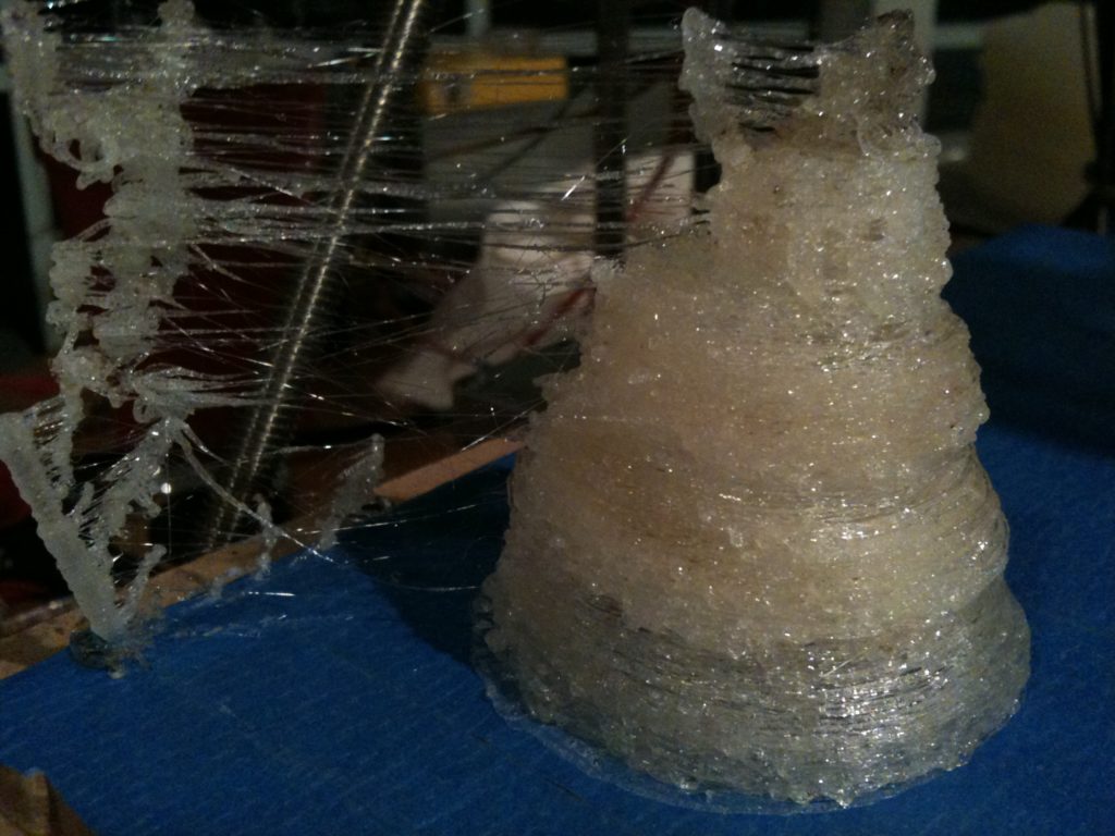
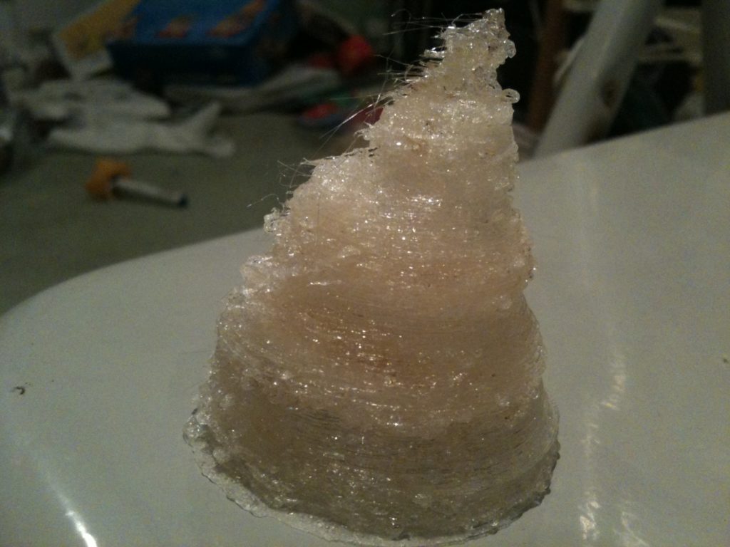
It’s hollow by design, so you can fit an LED around a watch battery inside it:

Since things were at least slightly recognizable as objects, and all of this was motivating me to RepRap more than printing more non-alcohol-tight minimugs, I decided to try printing one of the first things that I wanted to design for my RepRap (but that langfordw had beat me to the punch and designed first). I won’t say what it is yet – here’s a picture of the horrible-quality yet functional print:
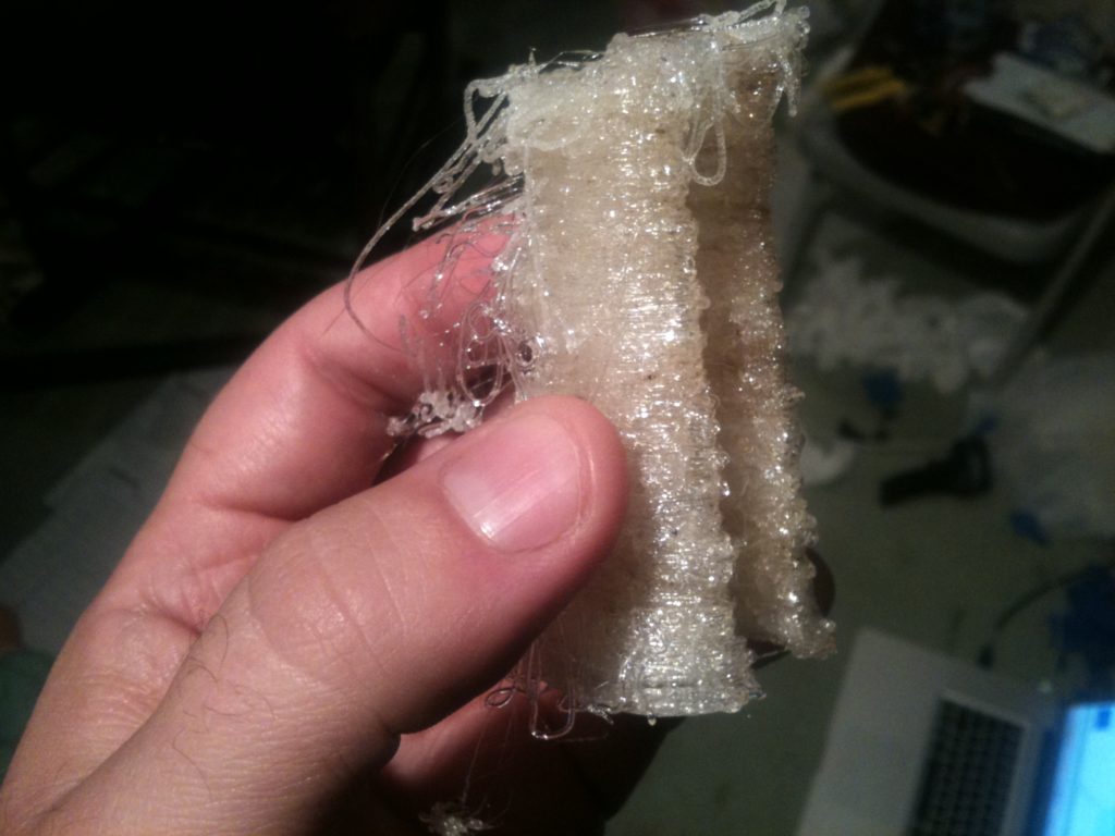
Can you guess what it is?

If you didn’t watch that video, I’ll tell you what it is: it’s a bag holder. More often than I’d like, I forget on Thursday night to take the trash out to the curb. So often I have several bags to take out, most of which end up packed to the top. I don’t mind the weight of the bags, but these red bag ties they make are like razor wire, digging through my palm as if to cut it in half. This bag holder lets you hold 5-6 full garbage bags without any pain!
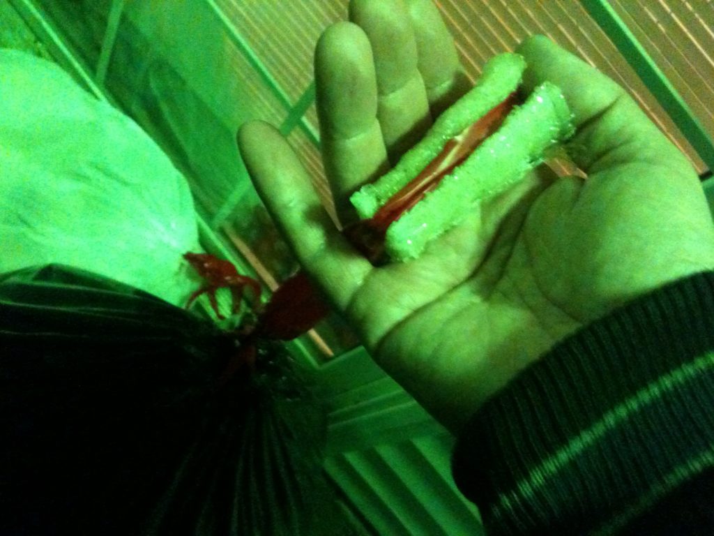
That’s the first useful thing I’ve printed with my Mendel RepRap! (But not hte first useful thing I’ve printed with anything, because with the RepStrap I was able to print parts for my Mendel!)

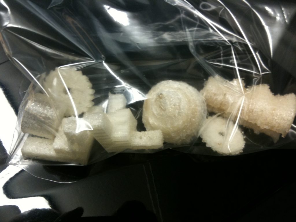
Having branched out from my myopic must-go-with-tradition-and-print-a-watertight-minimug focus to print multiple types of objects, that gave me something interesting to show people at work and elsewhere. I found myself carrying around a bunch of pieces in a large clear ziplock bag:
At some point in this (can’t remember where), I re-adjusted my E_STEPS_PER_MM setting. I measured the diameter of the hobbed part of the M8 bolt, saw 7.33mm and 7.31 mm, went with 7.32mm. I measured some recent stray printed filament, which came in at 0.51mm.. So I calculated an E_STEPS_PER_MM of 1.782303298, which seems to work well.

Ok, so now it was time to finally do X&Y calibrations based on the calibration object I’d printed. I’d printed out four versions of that object, and I measured parts on the first and last of them that should be 10mm, 20mm, and 40mm. Then for each of those measurements I figured out a multiplier for X, Y, and Z that would correct those values (although I didn’t use the Z value in the end). I averaged them together, looking for values that were out of whack and giving weight to objects that printed better, and came up with my final values.

In my configuration.h I’d originally had for x and y:

// For x and y, steps/mm = 400/(16.1798*pi), where
// 400 is the number of steps and 16.1798 is the
// radius in mm of the McMaster 57105K11 pulley.
// Answer: 7.8693

After calibrating, I now had:


//#define X_STEPS_PER_MM 7.8693
// Calibration experiments said multiply this
// by 0.9165
#define X_STEPS_PER_MM 7.2122
//#define Y_STEPS_PER_MM 7.8693
// Calibration experiments said multiply this
// by 0.9267
#define Y_STEPS_PER_MM 7.2924

Just for my own record, I’ll include the comments I have about Z_STEPS_PER_MM, but I didn’t change them here, even though the calibration experiments said to multiply it by 1.0193. This was my commented out original old calculation plus the brute force observation that I’d done back in July.


// For z, steps/mm-of-z-axis is
// (RPdiam / McMdiam) * (400 / 1.25),
// where RPdiam is the diameter of the
// RepRap'ed leadscrew pulley (which is
// ROUGHLY 1 1/8", or 28.575mm),
// McMdiam is the diameter of the
// McMaster 57105K11 pulley (which
// is 16.1798mm), 400 is the number of
// steps, and 1.25 is the pitch of the M8
// threaded rod used for the leadscrews.
// Answer: 565.1491
// ...
// ...but through experimentation by watching
// how many times the bolt went around,
// I ended up with:
//#define Z_STEPS_PER_MM 670
// 670 WAS GREAT but after 30mm, just a BIT too low
#define Z_STEPS_PER_MM 672

My X and Y calibrations now changed in the firmware code, I recompiled the firmware, uploaded it to my motherboard, and printed my fifth calibration object.

This one was great.
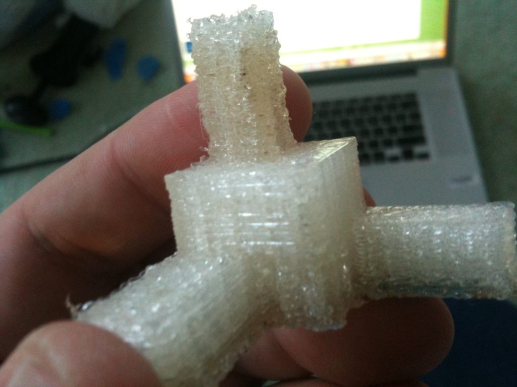
If it’s not clear what that calibration did, let me state it clearly. Previously when I’d tell it to move in the X direction, it would move too far. Similarly if I told it to move in Y, it moved too far as well.

This would certainly help explain not having watertight minimugs with the default settings:
1) Base of the mug is printed larger than it should be
2) Thickness of the printed plastic is still the same (same sized nozzle)
3) Thus, more space between the pieces of plastic that make up the base.

I tried printing a minimug with the default settings (no changed infill settings, etc – just the new calibration). Unfortunately I think this time the wire for the Y-Axis opto endstop came loose so the top was offset, but it was certainly watertight, even without setting changes.
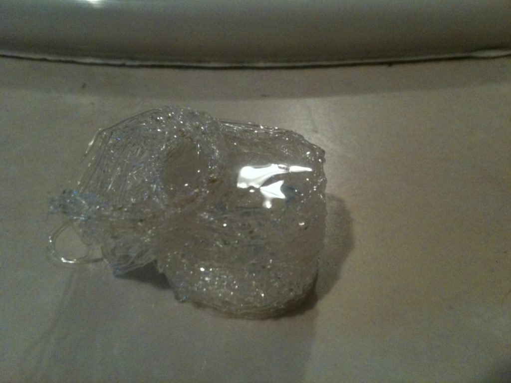
The next day, Alicia and I printed two minimugs that looked like great candiates for the toasting ceremony. Not wanting to mess with anything, we didn’t try filling them with water first. Actually the only reason we printed a second is because we were waiting for Laurie to come home to see.

With default settings:
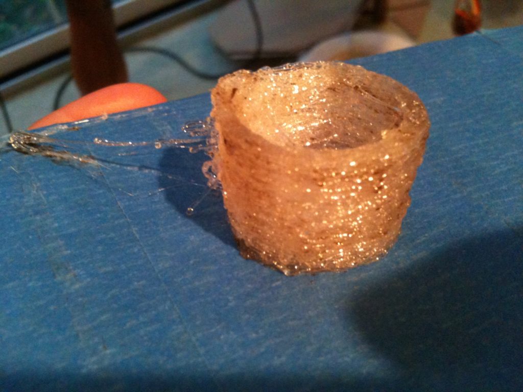
Laurie and I tested them both, and they both leaked alcohol. There’s still plenty of room for improvement though – this was just using the default RepRap Host settings – only 1 shell, the default infill, etc.

About a week later, I wanted to scratch an itch before going back to honing infill settings to try to get a tighter minimug. I wanted to print out an object that I designed.

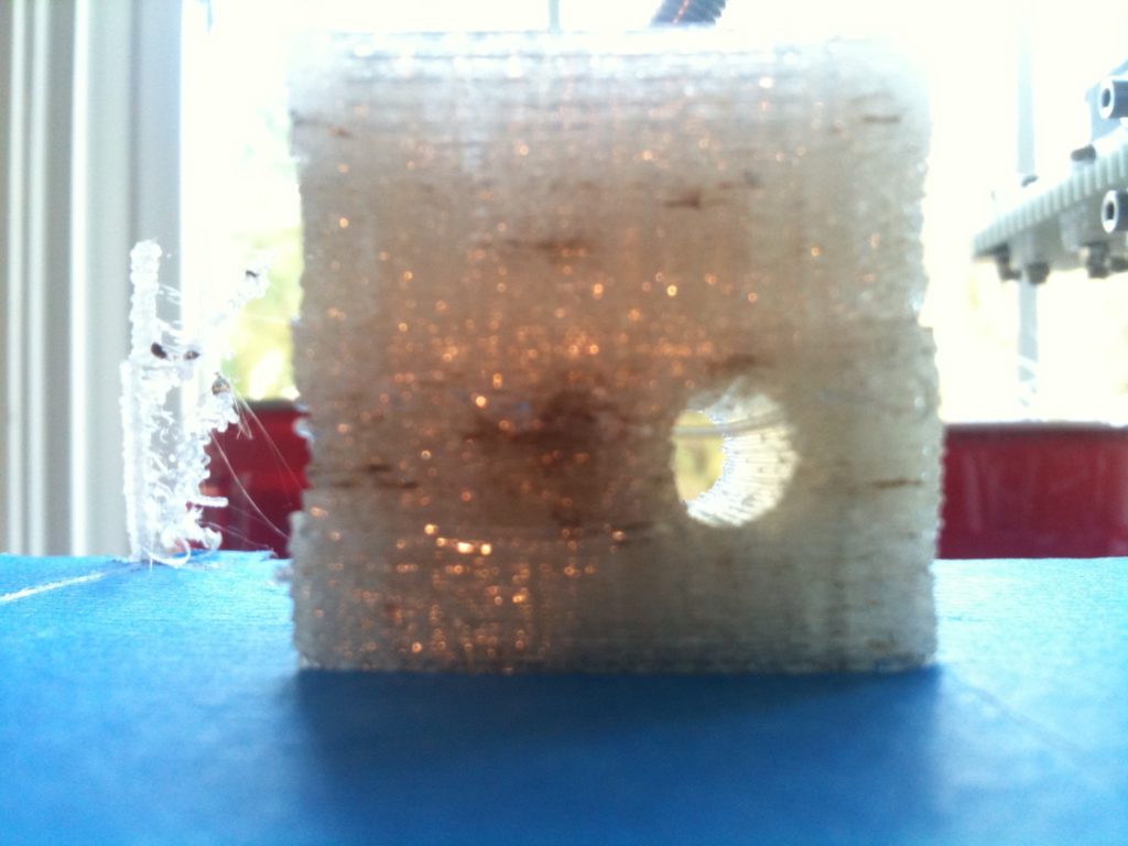
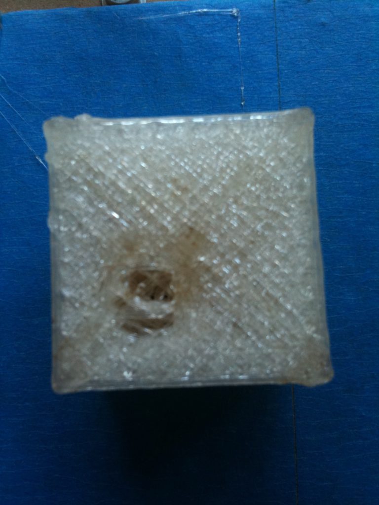
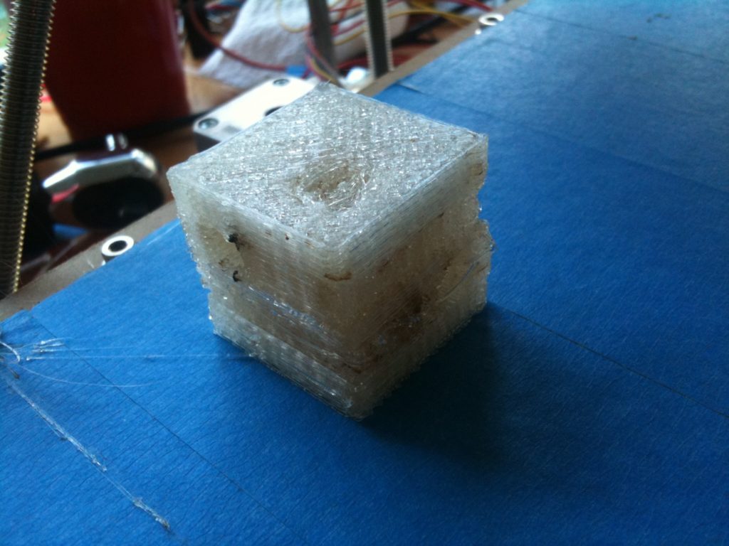
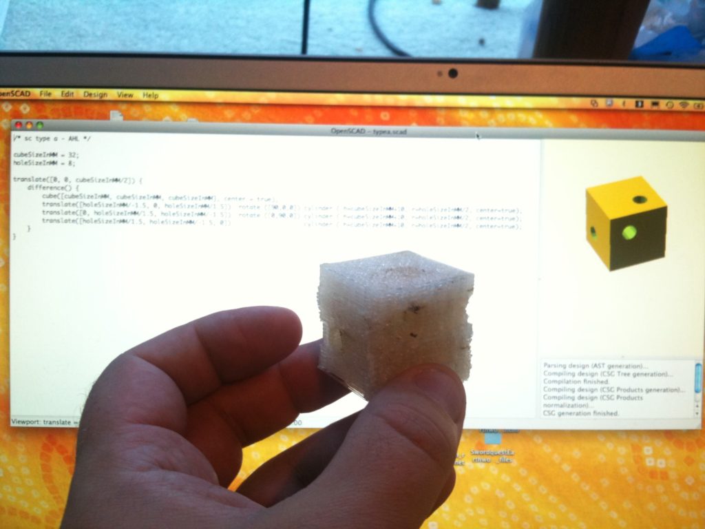
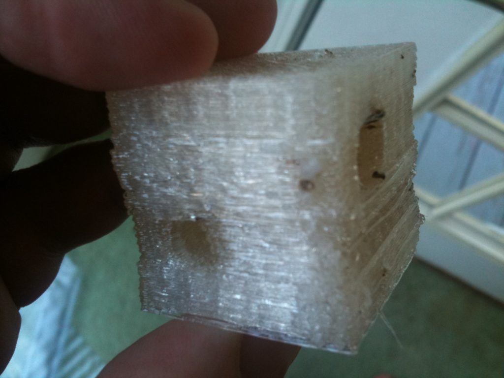
Now I’d designed one test object over a year ago with Google Sketchup, but that’s way too detailed to print out on the machine the way it is now. So instead I did a simple object in openscad. This is actually a part of something else I want to build, but I won’t go into the details of what it’s actually for in this blog. Suffice it to say, this is a cube with three 8mm cylinders subtracted from it. Three holes go through the cube, one affecting each face, and the tunnels don’t intersect at all.
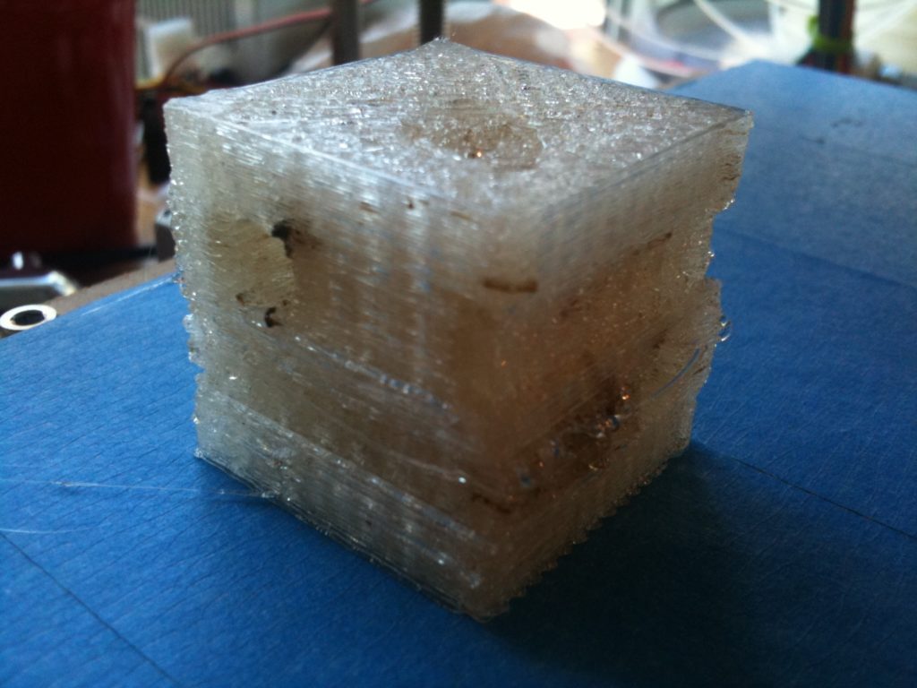
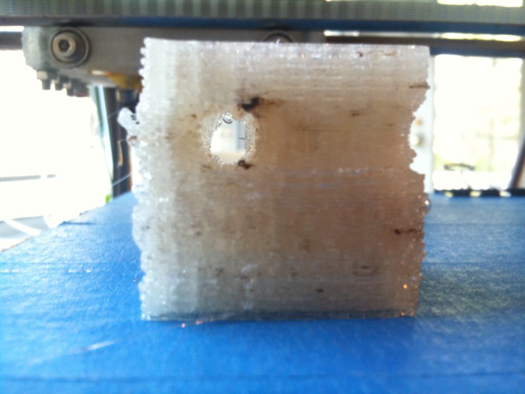
That’s supposed to be a hole going vertically down through the cube in the last pic, but that hole ends up poorly every time I print it.
Here’s the object in front of the openscad source that created it:
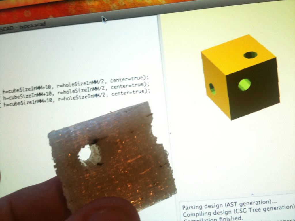
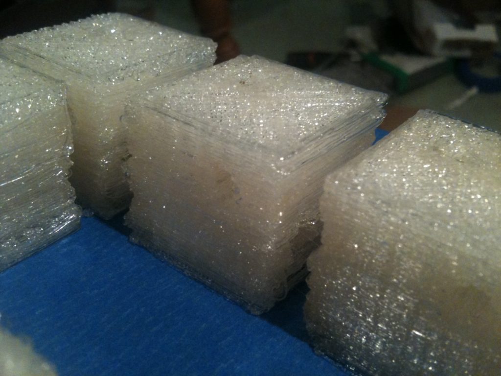
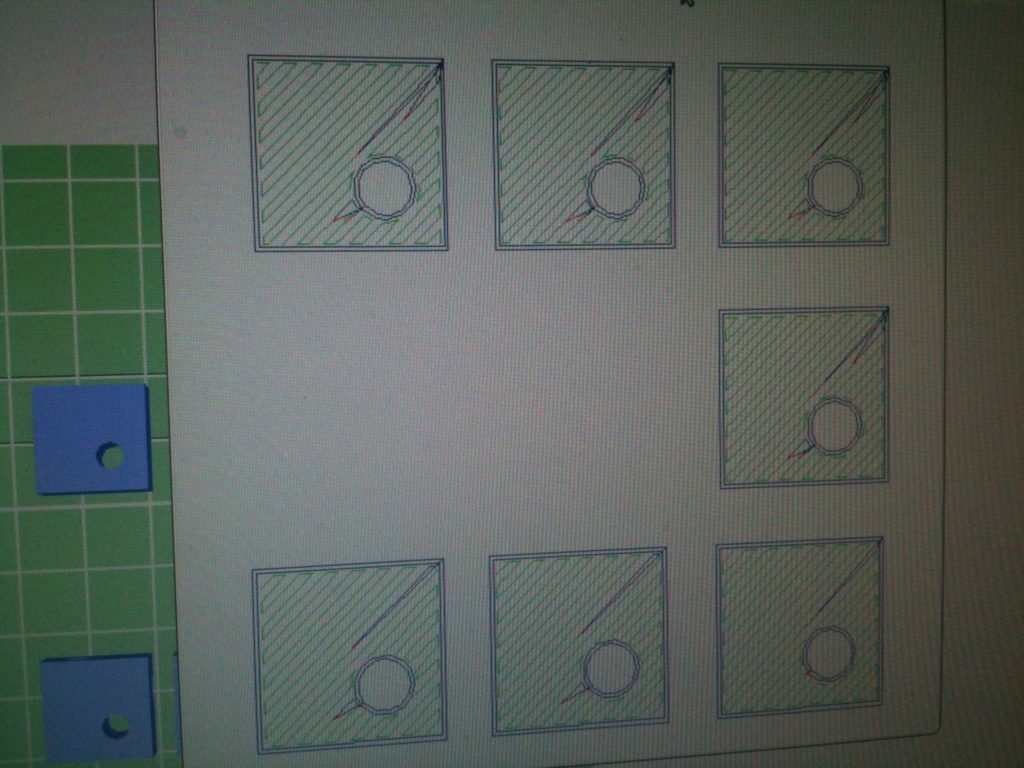
I needed seven more of these, so I created an RFO file that positioned 7 of these on the same bed. Unfortunately I spaced the ones on top too close together (actually looking at the next piece, I don’t think I did), and that combined with possible x-error accumulation seems to have led to them all melding into one piece. (If I do another sheet like this, I’ll add extra home commands by hand that home after each object during each layer).
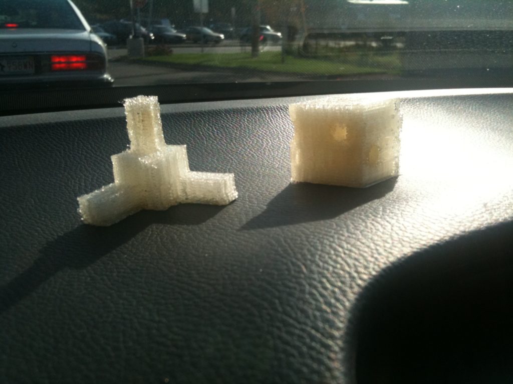
I printed three more by hand, one at a time. Some of those turned out excellent.
So, there ya go, I’m making great progress. It’s certainly more fun carrying around more objects than just mininugs.
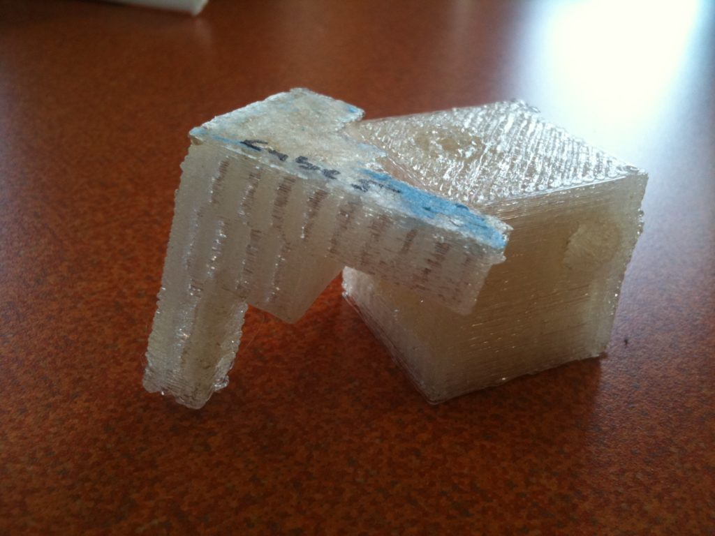
I finished this blog post before trick-or-treating! Woohoo! (I started typing this two days ago on Friday). Ok one last picture to enjoy: Alicia said that this looks like an elephant:
Update for the sake of an update.. State of my Mendel

Monday, September 20th, 2010

Enough time has gone by since my last post that many are wondering how things are going and why I haven’t updated yet, so I’ll post this update just for the sake of an update, rather than waiting for a moment-worthy moment. Work and the release of Halo: Reach aren’t helping either, so I might as well post this stuff now.

At the time of my last post, I’d just had my original non-geared Mendel extruder push the heater barrel out of the PTFE which was JB-welded to it (preventing me from easily fixing it). Here was what the barrel looked like:

And here a picture of the whole thing just lying on the bed:

I could have heated up the barrel outside of the PTFE to melt the PLA, pulled it out and cleared out the barrel the best that I could, and then use a soldering iron to melt some of the PLA in the PTFE, but I’d still be left with a PTFE insulator whose inner threads already deformed enough to let the heater barrel escape.. so I’d still have to try removing the PTFE (even though it’s JB-welded into the extruder). I’ve read some hints that that can be done with a chisel, but that didn’t sound too fun.

While I still may do some repair on that extruder down the road (as a backup), luckily I didn’t have to go down that road. Spacexula offered in the comment section of my last post to send me the printed parts for a Wade’s extruder (since I had the rest of the hardware ready already) as long as I agreed to print out and give away two once I’m up and printing. Since I was going to do that anyway, it was easy to say yes. One quick paypal for shipping later, this arrived in the mail:

(Thank you, Neil!) The four parts on the right were the parts for Wade’s extruder, while the others on the left were extras worth having spares of to help fill out the box and justify shipping. More pics:

Shiney!

Those bottom two holes on the last picture are where you screw in long M3 bolts that go through the PTFE insulator, so you don’t have to glue it on, so I won’t be in the same situation I was in with my last extruder.

One other picture I wanted to show (ok, two) before going on was the cool look of how the bottom flat part of the large gear looks from how this part was printed (on a shiner surface than the masking tape I’m using, that’s for sure.. Probably kapton or PET, on a heated bed?):

Ok.. So here’s what the back of the extruder looks like when assembled.

The idler bracket is the piece on the right, held on by four screws. There are supposed to be springs on there – the springs I bought from McMaster must have too many coils or something, because when I had the springs on there was no way the bolts would reach the trapped nuts on the other side.. I need to find suitable springs, but the springs aren’t 100% necessary (they even out pressure when the diameter of the filament changes or turns, etc).

The nut shown above was a temporary M8 nut I used initially until I had everything going, but I eventually replaced it with a nylock M8 nut so it’d stay on through the vibrations.

The big mistake here was even mounting the motor at this point at all. You need to mount the extruder on your Mendel first, before mounting the motor within it, because the screw sits directly below the motor (which was actually a problem for me, fitting the motor in, but I got it to work).

More pics.. Here’s the front of the extruder. The stepper motor shaft (with a flat filed onto it) can be seen in the middle of the small gear on the right. That turns the large gear on the left, which has a large M8 bolt trapped in it (the same one you saw a nut on in the back picture). Two skate bearings in the structure hold the nut so it can spin. The nut has a knurled notch cut into it, which I don’t think I did a very good job of, but it does the job at least for now. The plastic to be melted gets pushed between that M8 bolt on the big gear, and the third skate bearing in the idler block which is held on as seen in the pic above (with the four bolts that should have springs).

Here’s a close up of the bolts holding the PTFE insulator into the extruder:

And here’s a picture showing the two gears meshing from the side. Here you can see the filed down stepper shaft (knew I’d use that skill again), and the grub/set screw going through the trapped M3 nut in the gear to dig into that flat in the shaft:

I put it all together (without the heater barrel assembly) to see if the M8 bolt I’d cut could grip any plastic at all. It turns out it was good enough. Here is the motor just turning the gears:

…and here is the extruder actually pressing plastic filament through the extruder (again, without the heater barrel):

Ok so now I needed to create another heater barrel (so I could leave the one in my original extruder intact). I had two unsuccessful attempts at drilling out M6 rods – they came out way off to the side at the bottom. I spent a few days fixating on finally getting around to buying a mini-lathe, until I read up on what the differences between a wood lathe and a metal lathe were, and saw that a metal lathe would cost me at least around $400-$500. So I resisted that desire by doing what I’d attempted to do before – hollowing out a heater barrel by putting the barrel itself in my drill press, and lowering it onto a fixed drill bit (now an M3 bit, since I just purchased a metric drill bit set recently.. no more converting to imperial measurements).

With the barrel successfully drilled, it was time once again to wire up a heater barrel assembly. I’d previously made a checklist for myself of what tools/parts to have on hand to build one, but that was for the MakerBot RepStrap, so I made another for rebuilding the heater for my Mendel:

..except that those hose clamps don’t fit in the x carriage..

This time it took me 1 hour 12 minutes to get to a barrel in a nozzle wrapped with crimped nichrome, with a thermistor connected, and even wrapped in ceramic tape.

There was no convenient place on Wade’s extruder for me to mount a piece of stripboard with compatible headers for connecting to my Mendel, and I didn’t have the desire to spend lots of money on shipping for a few proper headers with polarized locking connections for this new extruder, so I just used some breakaway headers and created a small unpolarized plug inline to plug them into (which I’d later connect with tape):

I connected it all up again, and finally, I was extruding!

As I said, I was not using the right E_STEPS_PER_MM yet, so the speed was off.

Now with a geared extruder, I printed one mug that filled up 90% with water but then leaked (a JeffTry30 print). Then I did another of an earlier model (JeffTry22) which always looks good but has a horrible leaking bottom. This one didn’t print its shield well, so it resulted in burned blobs everywhere while it tried printing and kept dragging plastic where the shield should be.

I think I need to try using a hairdrier to heat up the bed a little before the first layer goes down, or adjust my z-opto-flag again to mash the plastic into the bed more.

Then one day (I don’t remember how long after that) I read that someone said the value usually used for E_STEPS_PER_MM for a standard Wade’s extruder was actually 2.02, which was larger than what I’d obtained from the spreadsheet I had. That night I got home extremely late, everyone was asleep, and I decided to upload new firmware with the correct value and try printing again.

Here’s a picture of the bottom of the mug being made.. Note the brown spots, because there was way too much plastic being output and the nozzle would plow through it, burning it at points.

Again the shield wasn’t printing correctly but I let it go on anyway. Here’s the ugly result, with a very thick/tight bottom:

That was also a JeffTry30 (but again, now with 2.02 for E_STEPS_PER_MM). I went into the bathroom, and filmed this:

Sadly, the next morning was not a time for celebration. I actually tried filling the mug with my as-of-yet-undisclosed drink, and it sadly spilled all over the table. Now would be a horrible time to find out that alcohol dissolves PLA or something, wouldn’t it? 🙂

Haven’t had time yet since then to print another, and I’m going to be slowed up a bit by events over the next few weeks.

One of which, by the way, is Makerfaire NY, on September 25-26, 2010. I’m up in the Boston area, but I’ll be heading down Friday night (the 24th) with my Dad, we’ll stay at my brother’s, and the three of us will check it out Saturday. Mid-summer I’d considered bringing my Mendel down, but I deliberately let the deadline for registering pass, which I’m glad I did because while deadlines do help motivate progress on projects, they also tend to add stress, and in this case I’d rather see others’ RepRaps and walk around the faire than stand in a booth explaining why I still don’t have it calibrated correctly for a watertight minimug. 😀

So there you go – the most recent state of my Mendel. More later (after I’ve had a few weeks to get a few hundred hours of Halo: Reach under my belt, which is another distraction, but a welcome one). 🙂