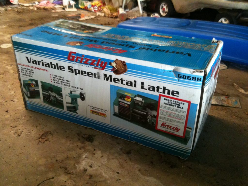
My metal lathe arrives! (back at the end of January 2011)
First, let me say that I’m cursed by the fact that so far I’ve blogged everything I’ve done with my RepRap, and I don’t want to stop now. I’m currently behind by about 9-10 months! My last post was in May of 2011 – today is October 2, 2011. (This feels like debt!) What makes it worse is there’s a whole bunch of pain in those months, but I pride myself on posting my failures as well as my successes, so I’ll post it all – but know that I’m not doing as bad now as these posts are going to show! 🙂
Ok.. So.. Back at the end of January 2011, my birthday gift arrived – a metal lathe! Yes, I know that today there are so many people with RepRaps that everyone just buys pre-made hot ends and never experiments anymore, but screw that – I wanted a lathe. I was so sick of trying workarounds that involved doing strange things with my drill press, which were in fact clearly lathe tasks.
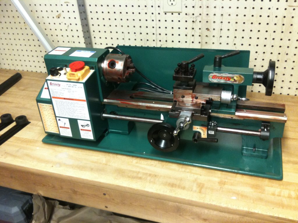
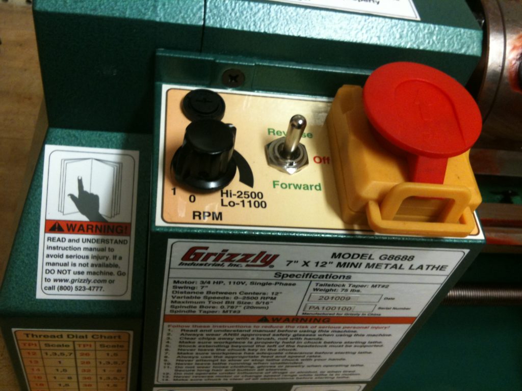
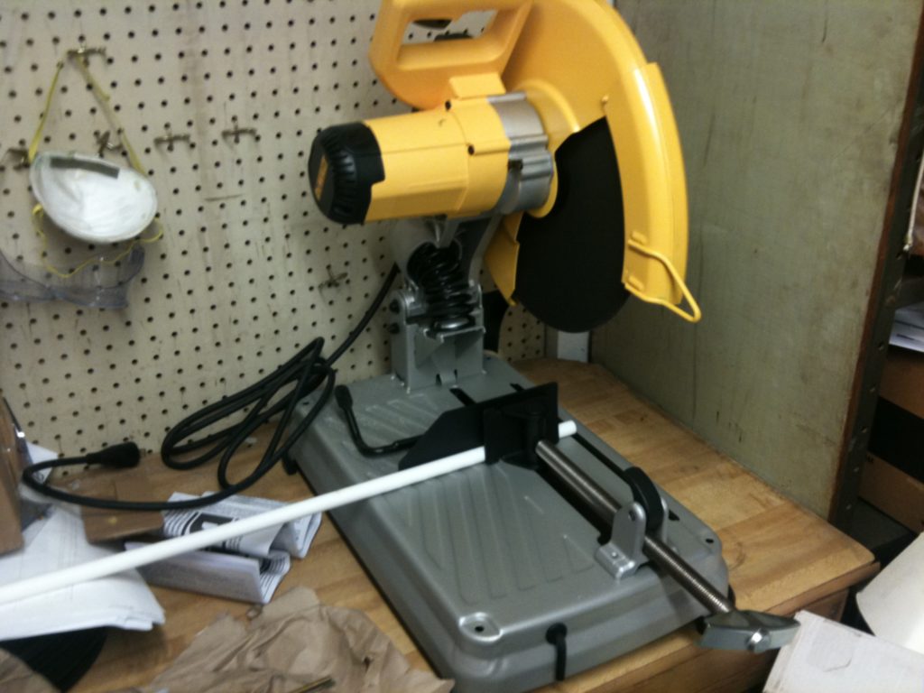
So, it arrived:
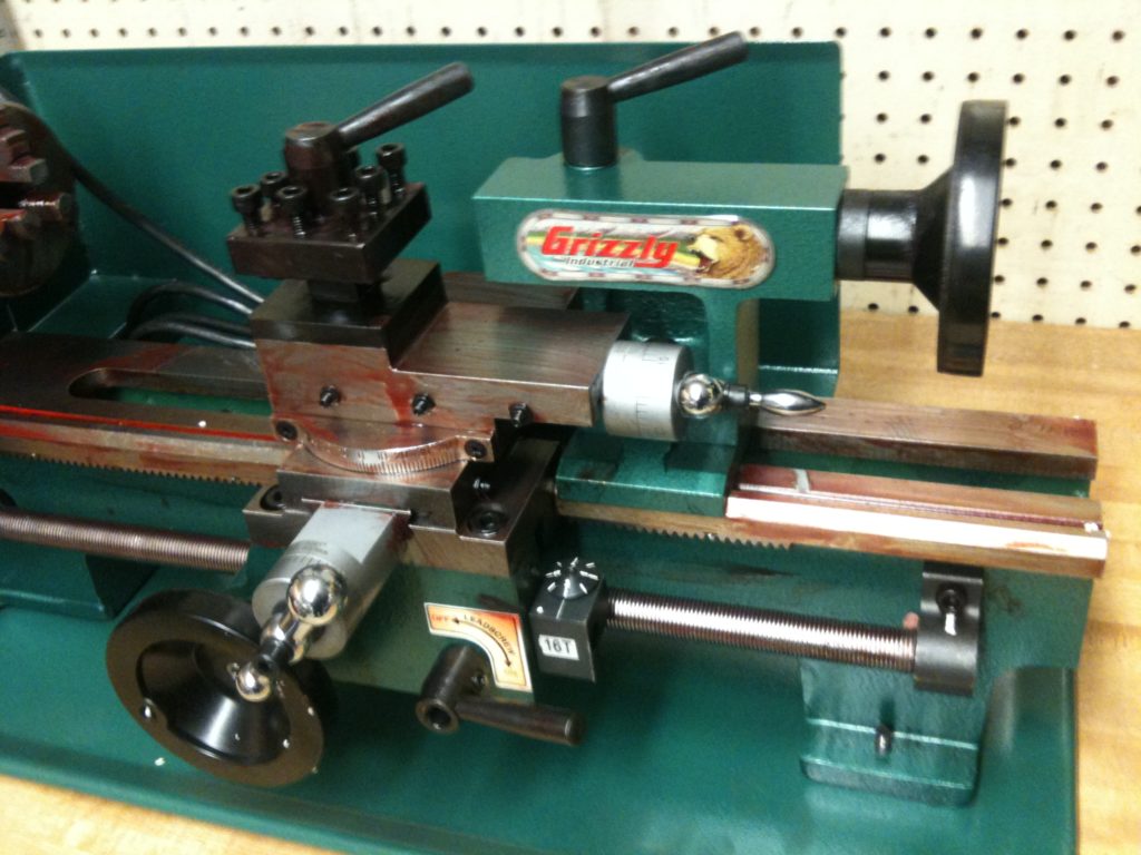
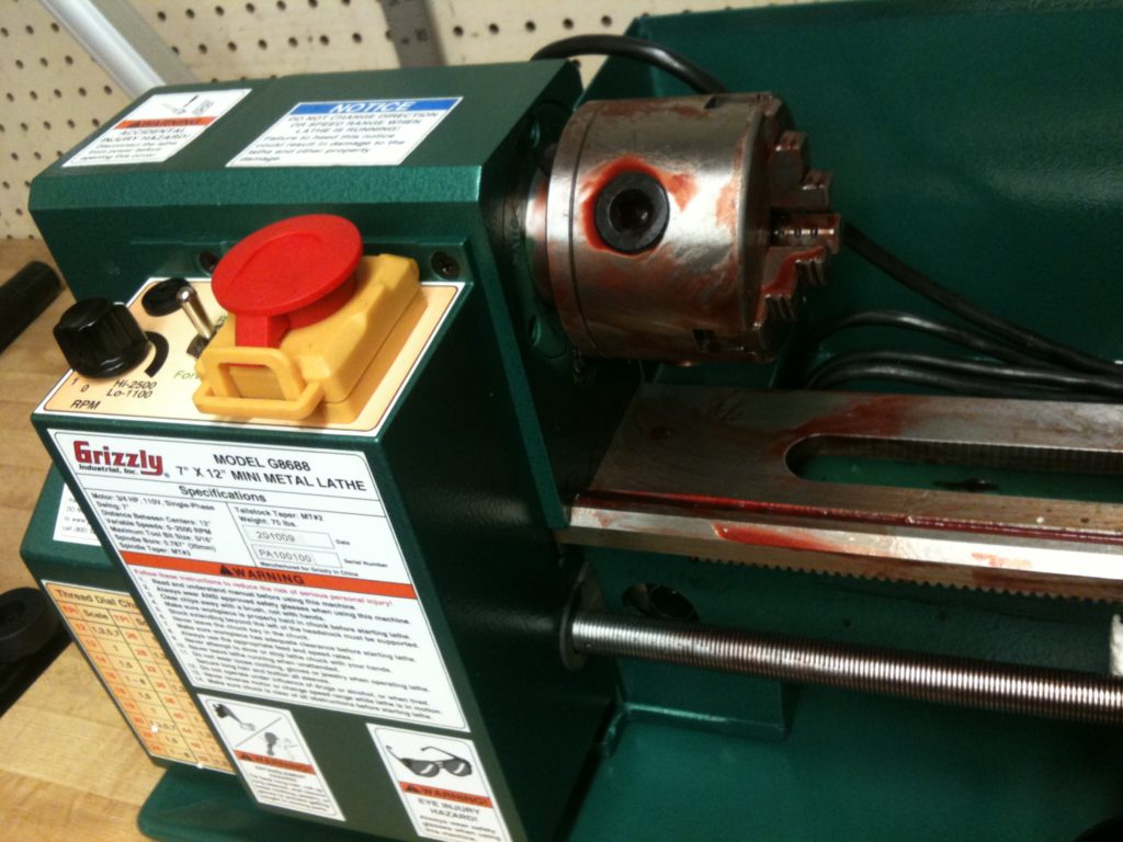
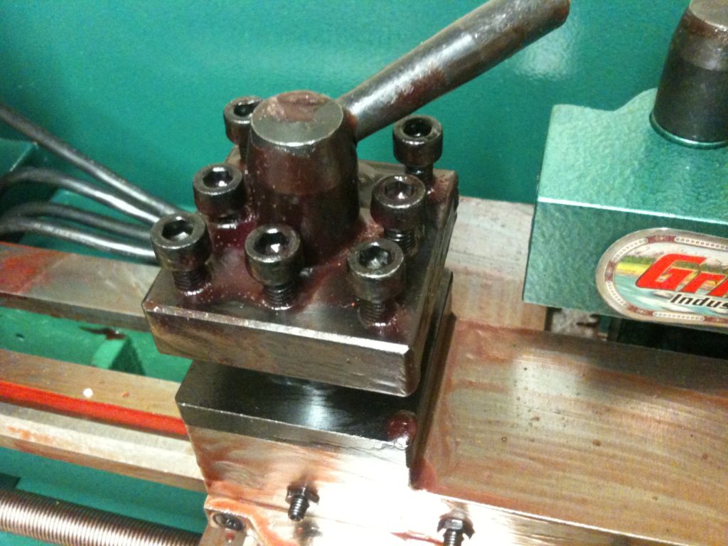
As you can see it was covered with packing grease, which happened to be a deep crimson red, which felt at least a little unsettling, this being a powerful lathe and all…
After a whole lot of cleaning off of grease, Alicia stood guard over my first test run:
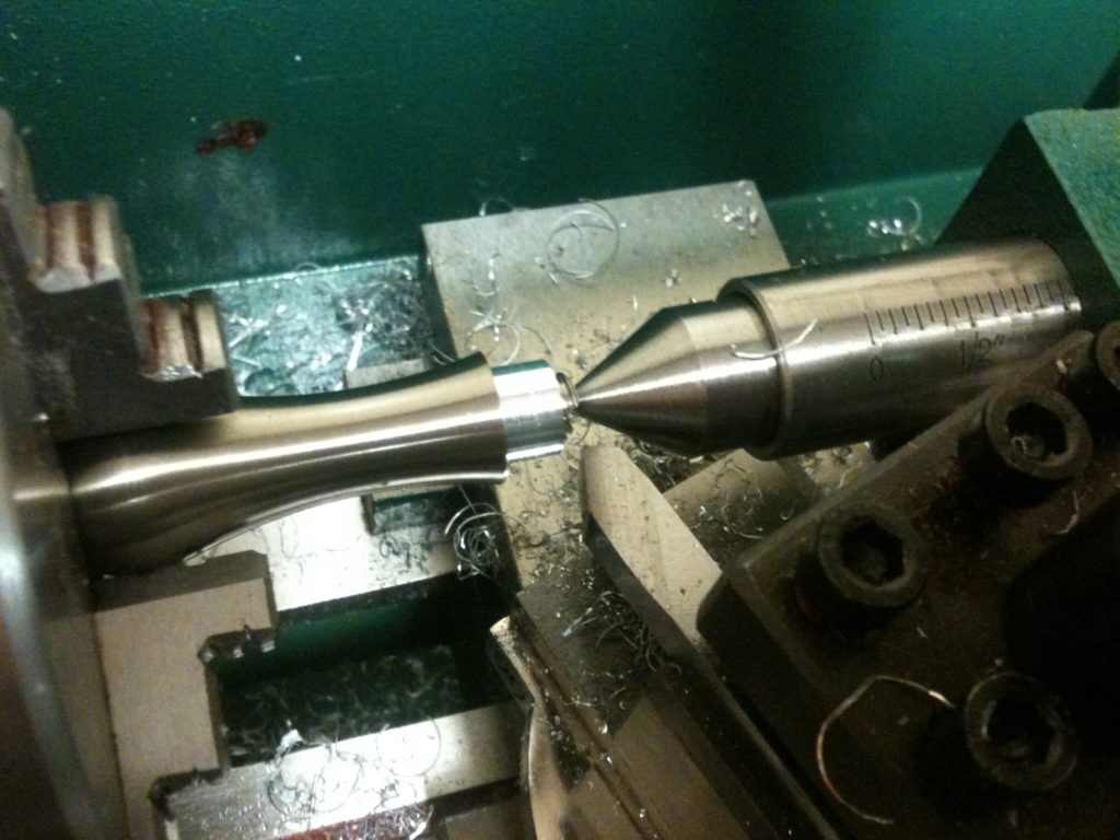
Next I practiced using the lathe with some machinable wax, and made my first thing with the lathe:
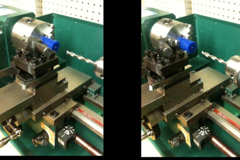
And here are two more pictures just for the hell of it, the 2nd one 3D (cross your eyes to get the images to line up):
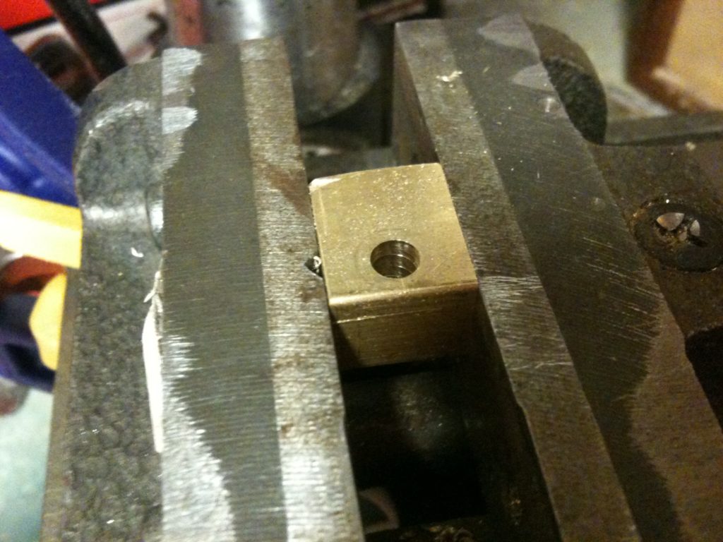
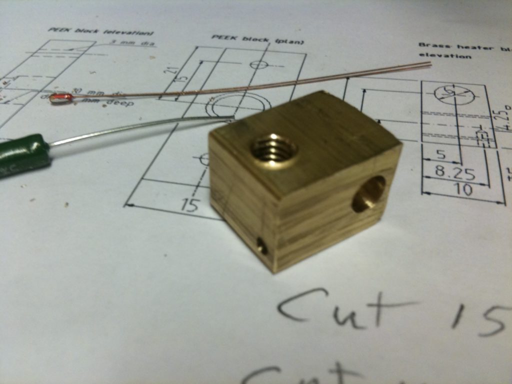
I then left the lathe for a while to make a heater block for my extruder (so I’d no longer ever have to wrap nichrome wire again).
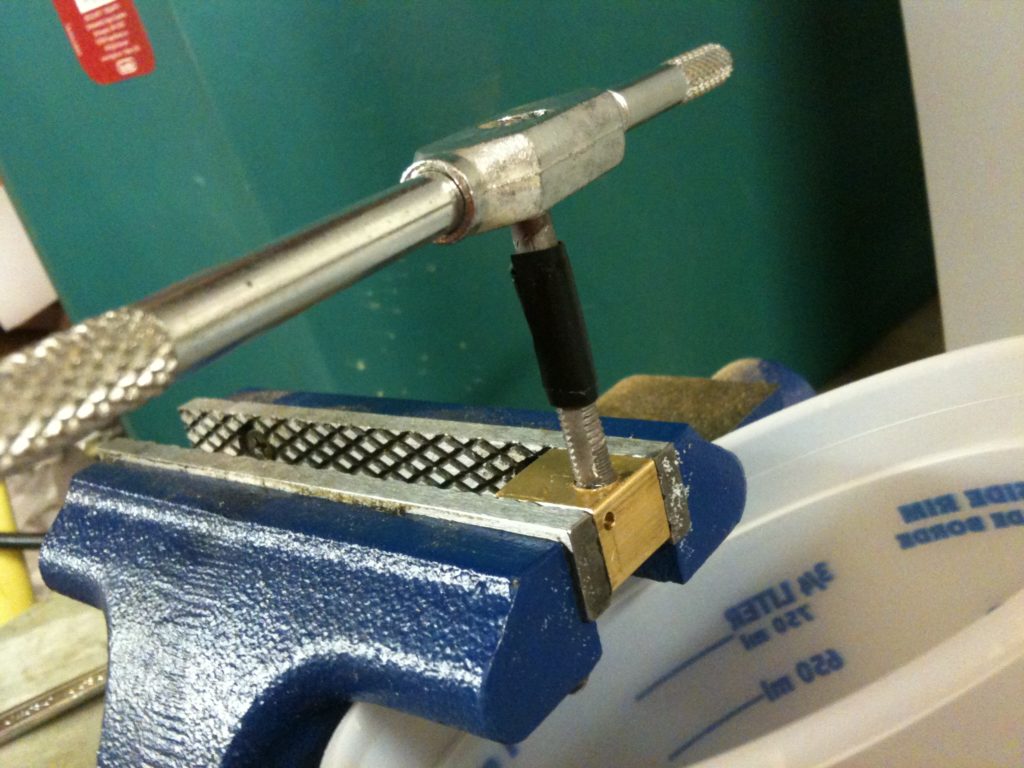
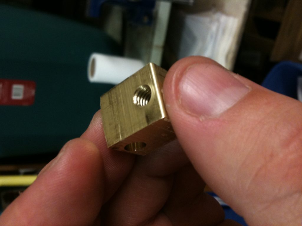
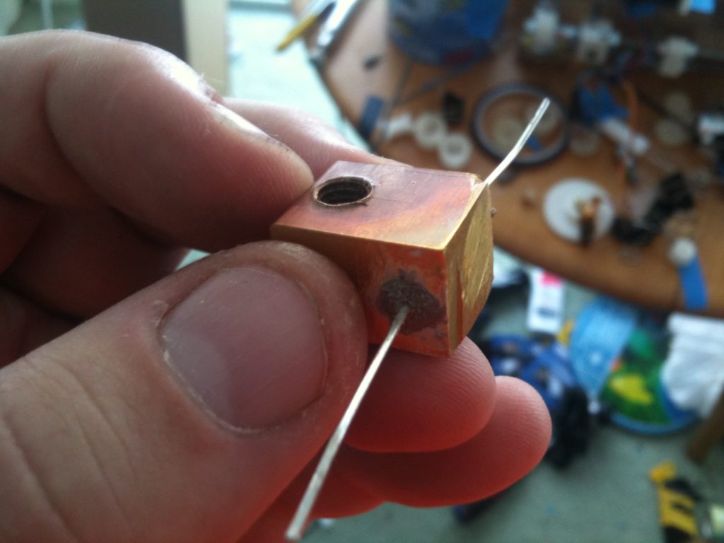
Then I tapped the hole to M6. Adrian’s original extruder nozzle was threaded (and thus the heater block was threaded too). A later heater block of his (which I eventually make months later) is smooth instead, using just an interference fit. This particular heater block I ended up using on my old M6 heater barrel. Here’s what the tapping looks like for those unfamiliar with it.
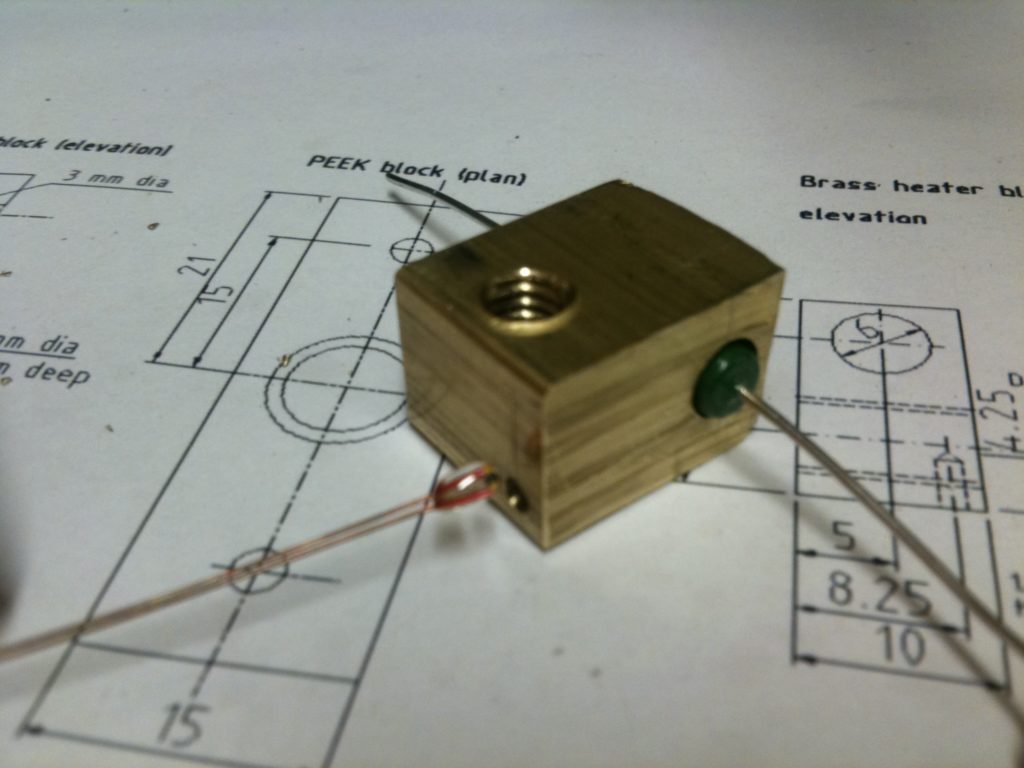
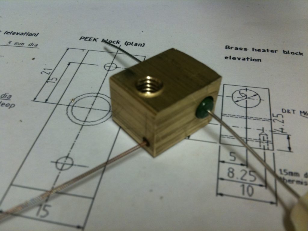
Then it was time to assemble it. A large resistor goes through the large untapped hole, and the end of the thermistor goes in the smaller hole.
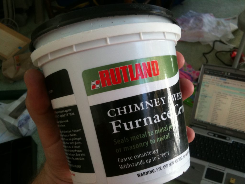
The resistor needed to be cemented into the heater block, which required me to open the fire cement that I’d bought a year earlier for one of the earliest designs of extruder that I thought I’d make.
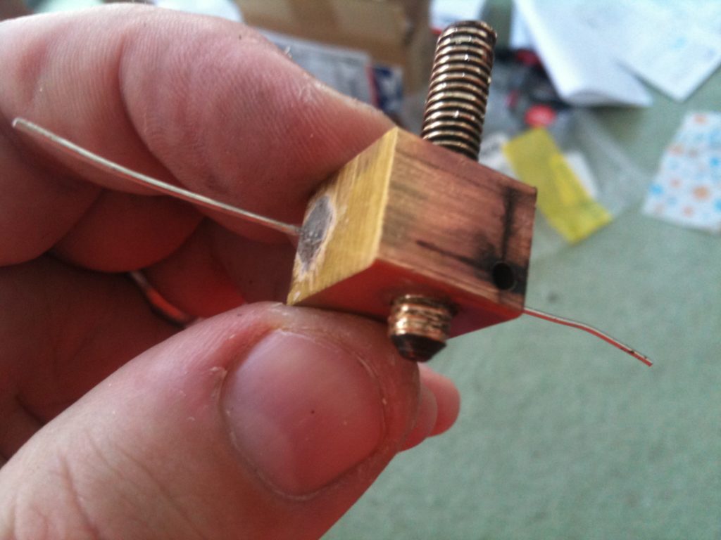
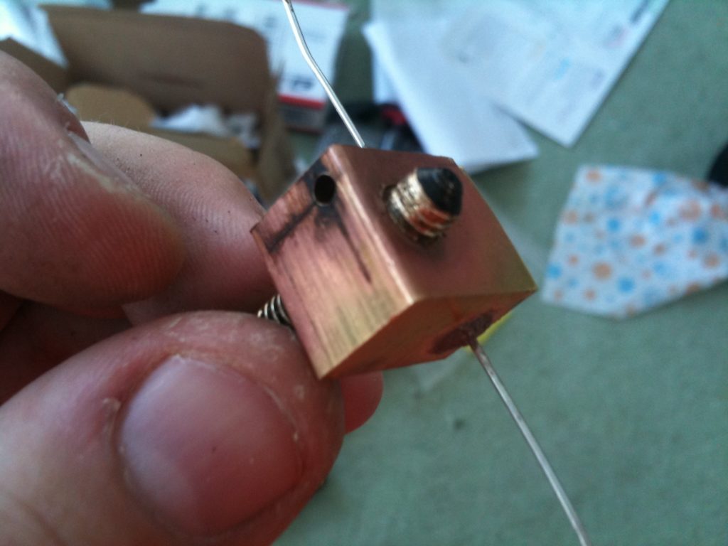
I took out the thermistor, packed up the resister hole with some of the cement, put it in the oven at 200°C (around 392°F) for like 15 minutes, and here was the result.
Here’s a picture of it screwed onto my old-style heater barrel (which I’d made on the drill press, but which still works today):
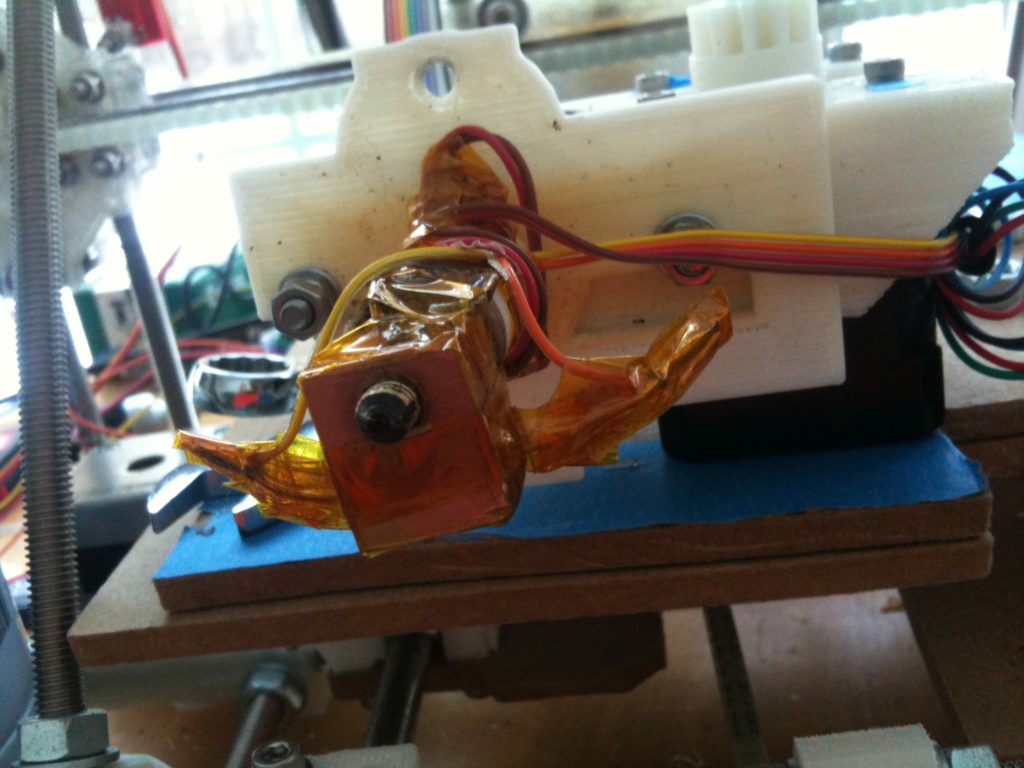
…and then here’s the whole thing in my Wade’s extruder, with the thermistor back in, all wired up with crimped bootlace ferrules, and wrapped in kapton tape:
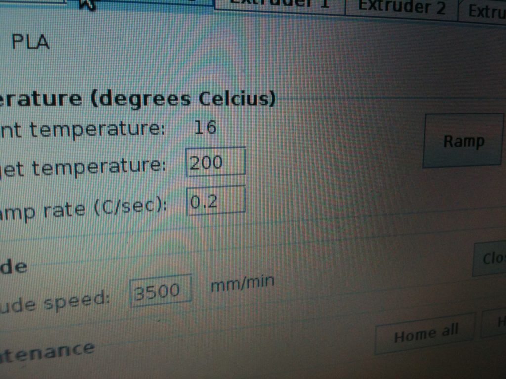
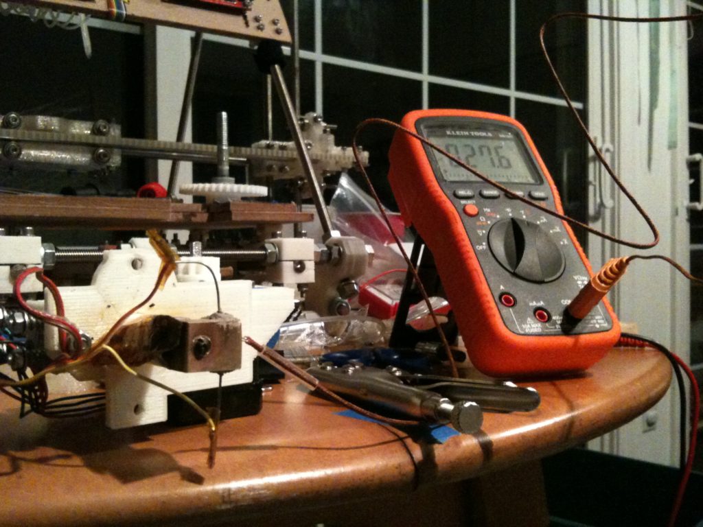
Now it was time to test it! I hooked it all up, got very excited at the prospect of never having to rewrap a heater barrel with nichrome wire again, and tried heating up the heater barrel. And? And.. nothing. It wouldn’t heat at all. I was trying to bring it to 200°C but it stayed around 16-17°C:
So I double checked everything and eventually found……. ….that I had accidentally ordered the wrong resistors! AAGGHH!! I had accidentally ordered 6.8Kohms resistors instead of 6.8 ohms resistors. I’d have to order new resistors and redo the entire heater block, fire cement and all. Grrrrrr…
Ok, so I ordered the resistors, then the next day – back to lathe work.
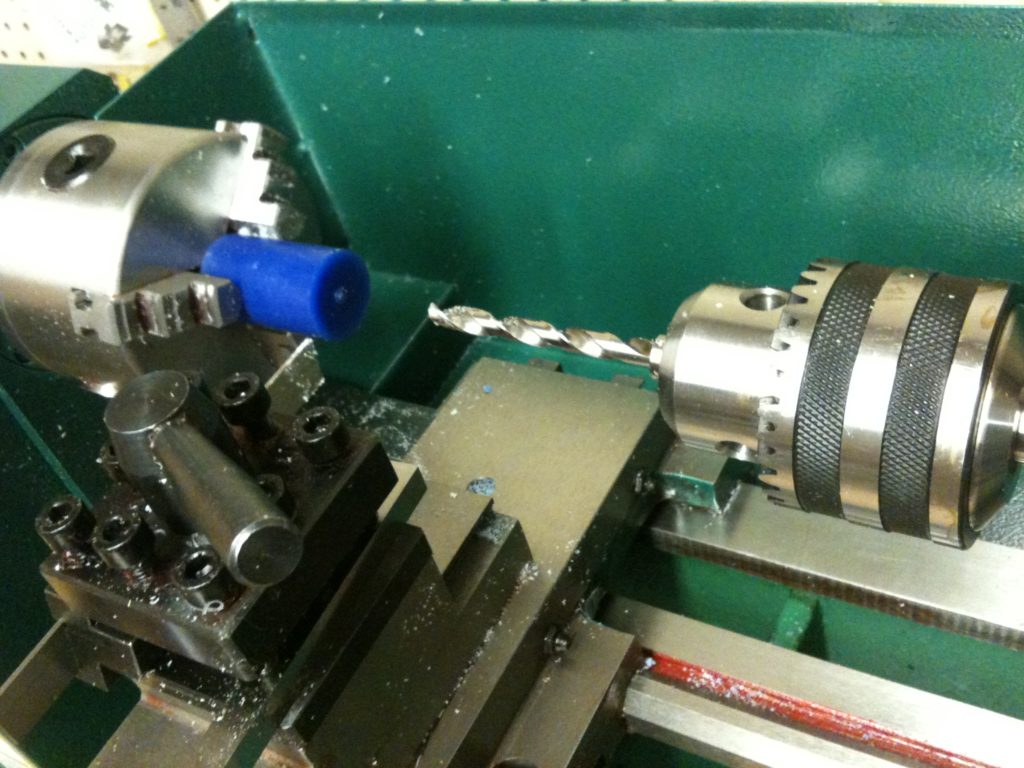
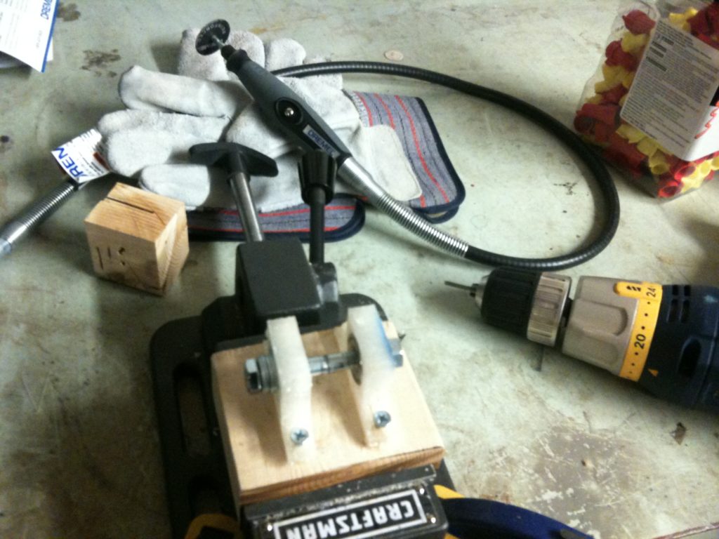
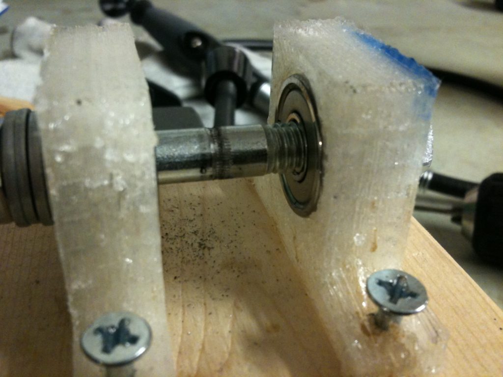
Ok, so the main reason I wanted a metal lathe was to be able to make heater barrels better than the ones I’d been making. To drill a 0.5mm hole in the end of the barrel, I’d need to be able to hold onto one of these tiny 0.5mm drill bits somehow in the tailstock of my lathe (so it can be slowly pressed into the spinning barrel, cutting the hole). Before my lathe I’d been able to hold the 0.5mm drill bits in a vise in my drill press but now it had to be held somehow in the tailstock. The thing is, the chuck in my tailstock was way, way too big to hold those drill bits.
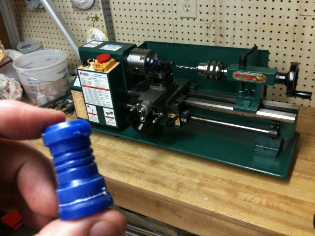
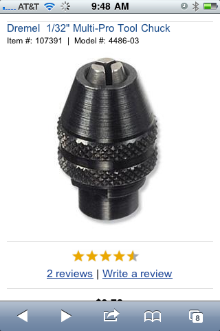
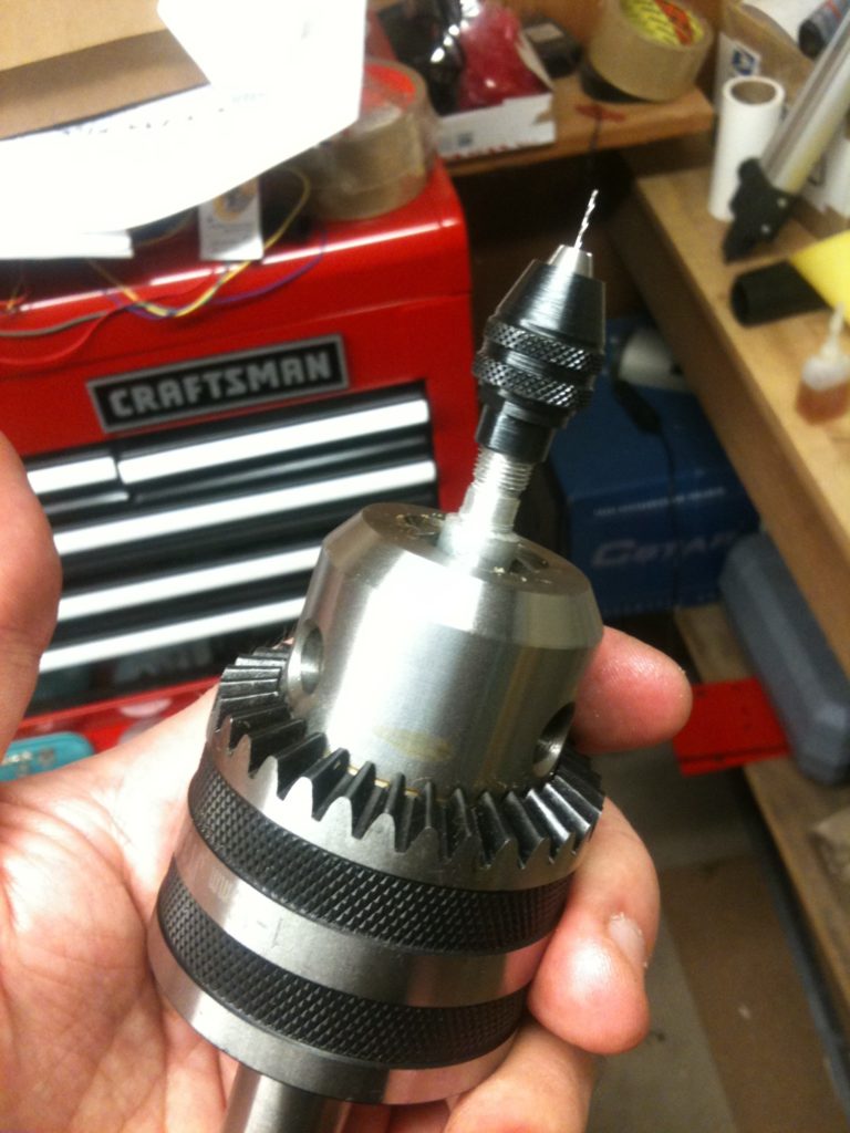
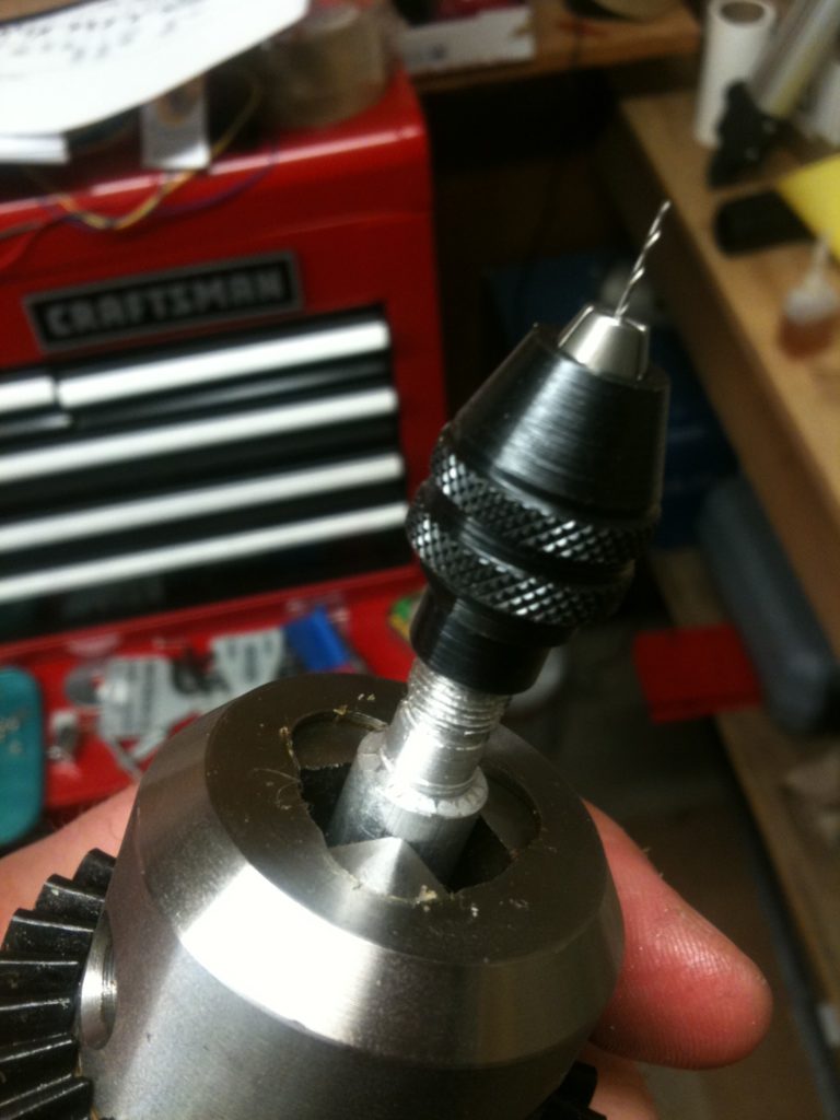
I’d wanted to make a heater barrel that day (a Saturday). The smallest thing I could typically find in stores around me were Dremel drill bits (and the collets that hold them) that were way too big (1/32″, around 0.8mm). But then I saw this Dremel 3-jaw chuck online.. It said it only went down to 1/32″ as well, but then I found a European ad for the same product that said it would hold something as small as 0.4mm, which had me believe it would work fine. Here’s what the 3-jaw chuck looked like:
I called a bunch of hardware stores around me and found one that had it in stock. I drove over, wanting to do all of this that day, bought it, and returned home. I figured that I’d hold THIS 3-jaw chuck in the large chuck in the tailstock of my lathe, and that’d be that. But it turned out not to be so easy.
I’m going to show the result video first, because I think it makes a better presentation that way. Watch this video:
Man that made me happy. Yes, I know there are other ways to hold small drill bits (and in fact just this week I finally placed an order for a mini pin vise that can hold a #80 drill bit (0.0135″, or 0.343 mm)), but the cool part was that I had a want to do that THAT day, and I was able to, by making that part with my lathe (including learning to cut threads, which was really cool).
Here’s how I built that.
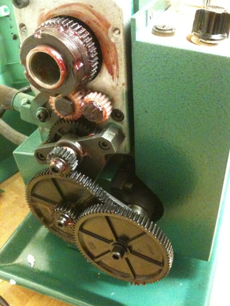
First, I knew I had to cut threads with the lathe (my tap&die kit is metric, and probably wouldn’t cut threads that small anyway). I determined what the threading was on my Dremel shaft by inspection first, then I confirmed it by Googling it and finding out that it was 40 threads per inch. So the first thing I had to do was open up the panel on the left hand side of my lathe and change some gears to make the leadscrew turn at the correct rate to cut 40 threads per inch. Here’s what the original gear configuration looked like before I changed it:
(That’s a 20 toothed gear for A, 80 toothed gear for B, 20 toothed gear for C, and an 80 toothed gear for D).
I followed the lathe manual’s instructions on changing up the gears for 40 threads per inch, which involved removing one of the gears and changing some.
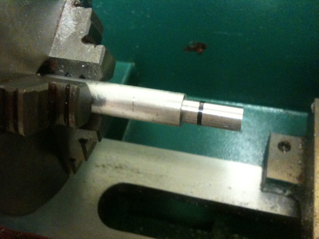
Then I put a piece of aluminum rod in and turned it down to the correct diameter. I marked where the threads needed to go with black marker.
I put in the right cutting tool for cutting threads and lined it up perpendicular to the piece. I started cutting the threads, one pass at a time, and frequently went back to check whether a normal Dremel cover (which has no center axle) would screw on or not yet.
Thread cutting is pretty fun – it’s an interesting experience. I wanted to document it and show exactly what steps I go through to do it, so here’s a pretty detailed video showing a few passes of cutting threads and what I do to cut them. I like this next video:
Then after a while I ran into a problem where it seems the diameter of the cut threads was actually larger than it was before cutting, as if the metal was swelling or something (maybe it’s because it’s aluminum?). I’m all ears if any experienced lathe operators want to explain this:
Well I think what I did after that was actually file down the threads a bit, and eventually, I got it just right:
That allowed a standard Dremel cover to be screwed on, but since it wasn’t a hollow shaft yet, the Dremel chuck couldn’t screw on (because if its inner axle). So here I used a center drill to start the hole that I’d ultimately cut with regular drill bits:
And then, success!
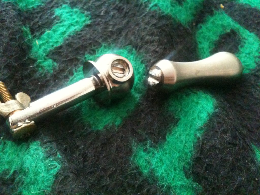
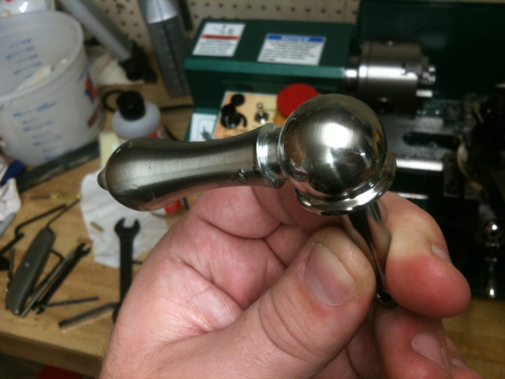
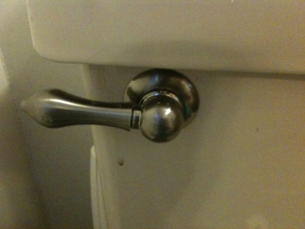
Here I’ll quickly mention one non-RepRap thing that I did with my lathe right after that. The handle on my toilet broke, leaving it looking like this:
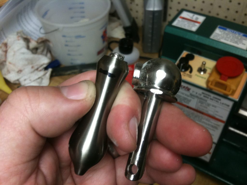
Well I decided I didn’t need it to be pretty, but I wanted to figure out a way to fit those two back together. I didn’t even need to thread one side and tap the other – it’d be fine if I just had a section of smooth rod that I could hammer into a slightly smaller hole on the base for an interference fit. It was, of course, just an excuse to cut something else on my lathe. 🙂
Fixed!
One week passed, and the new (correct) resistors that I ordered for my heater block came in. The first thing I had to was drill out the old resistor that I’d cemented in the block.
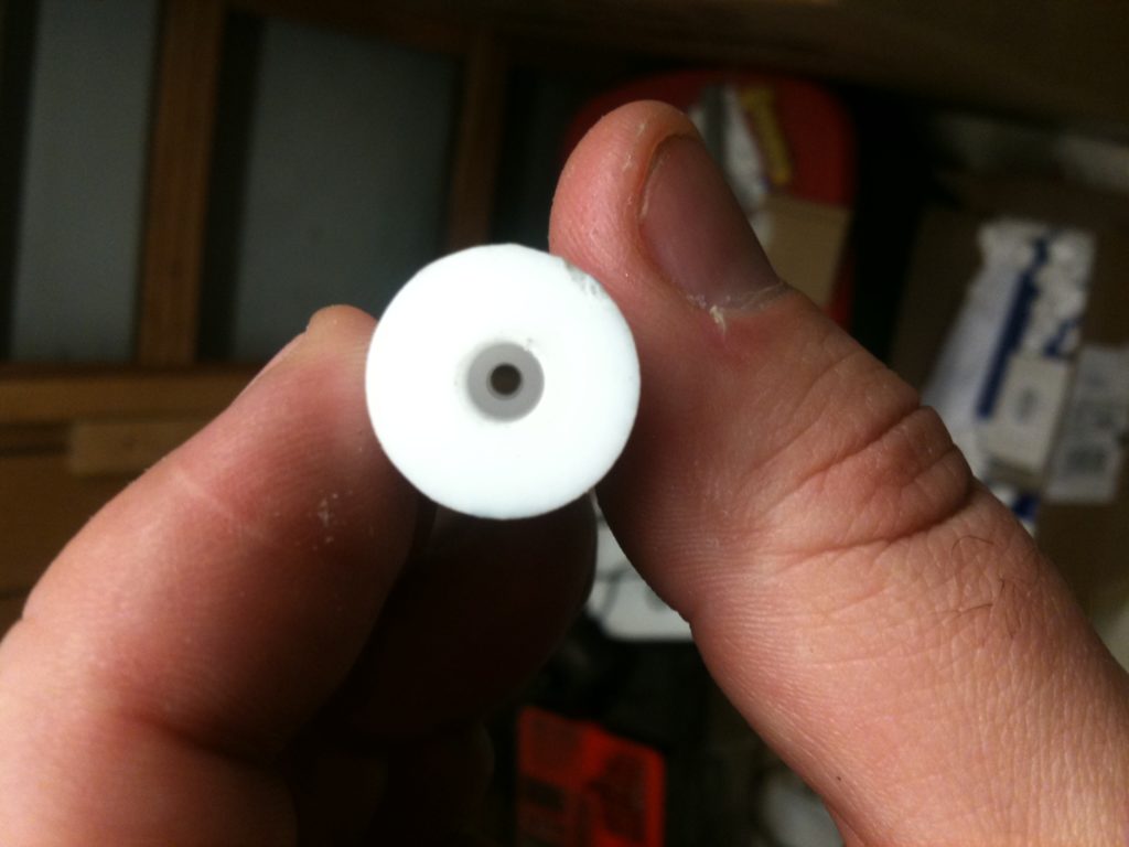
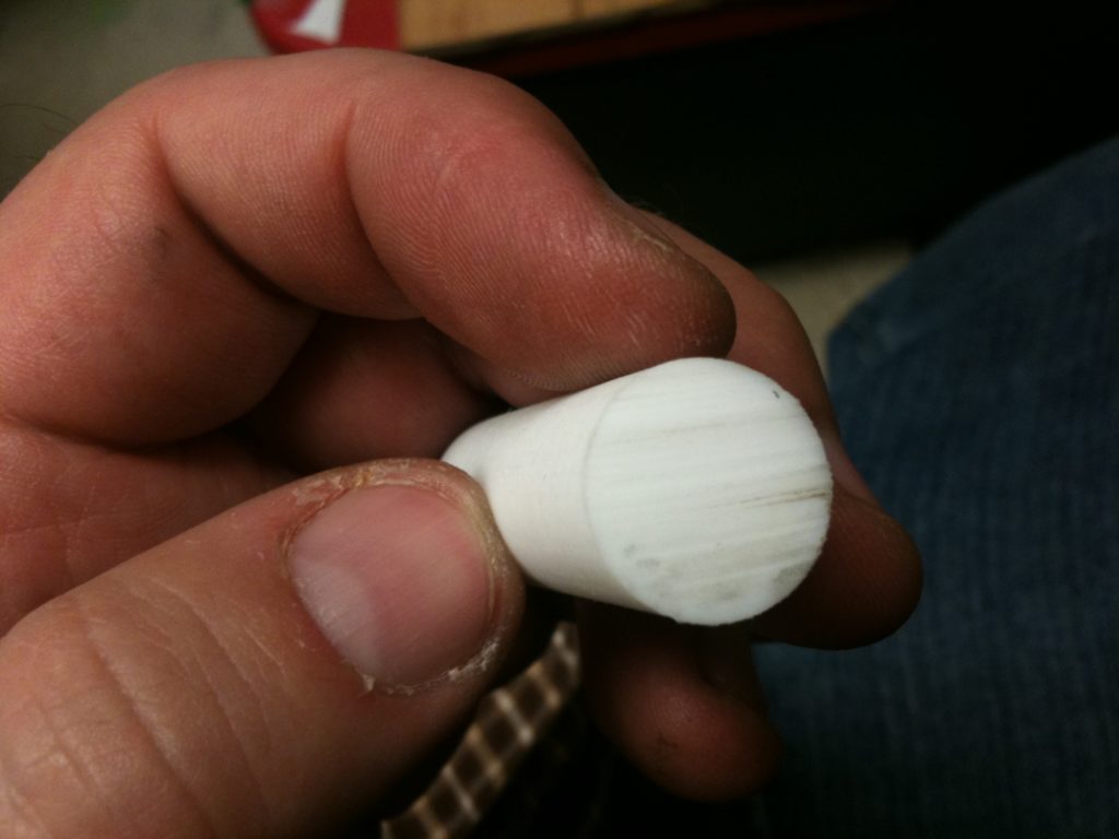
Then, while I was downstairs, I made a perfect PTFE insulator on my lathe (feel free to go back and compare it to the off-center horrible insulators I’d made in the past on my drill press):
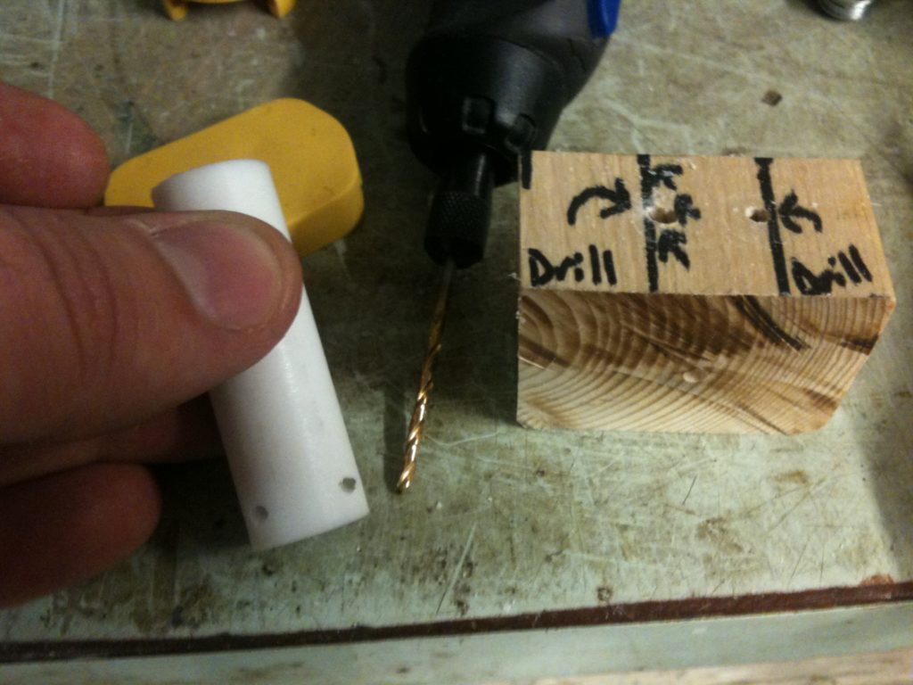
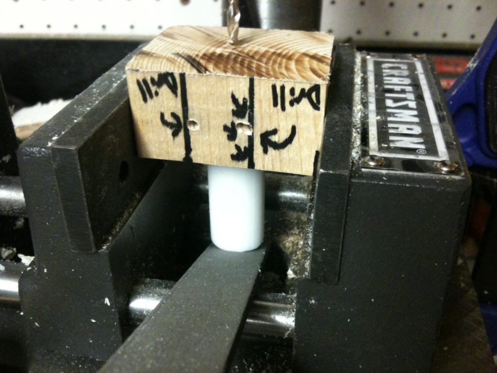
I then drilled holes for mounting it in Wade’s extruder with the jig that I’d made previously:
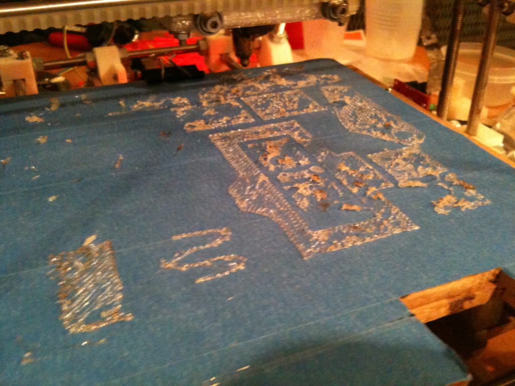
It was at this point that I made the CRITICALLY WRONG HORRIBLE MISTAKE OF NOT USING THIS PTFE INSULATOR! I got lazy, and decided I’d use the previous one, since it still seemed to have pretty good tension when I screwed it in. (Jeff contains his anger as he types this). This turned out to be a monumental mistake that cost me dearly.. but you won’t read about that until my next blog post.
Not realizing the mistake I was making (the affects of which I wouldn’t feel for another whole day), I hooked up everything again (the heater block with the new resistor, but mounted in my OLD PTFE insulator), and tried testing the heater block.
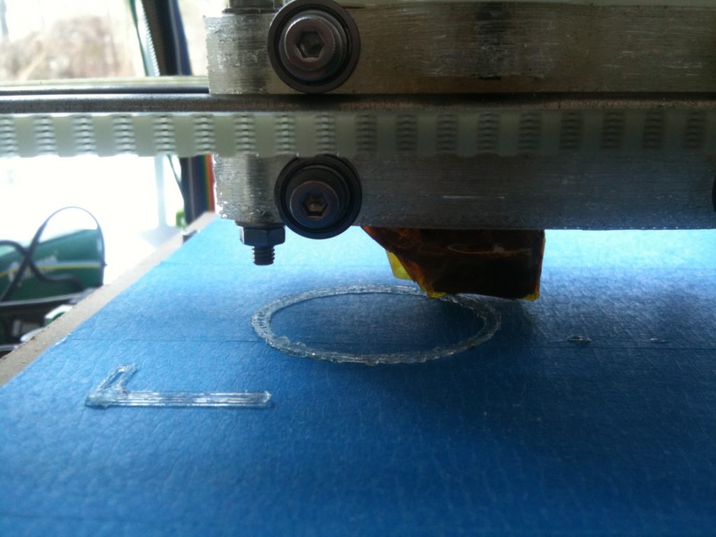
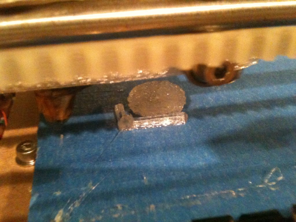
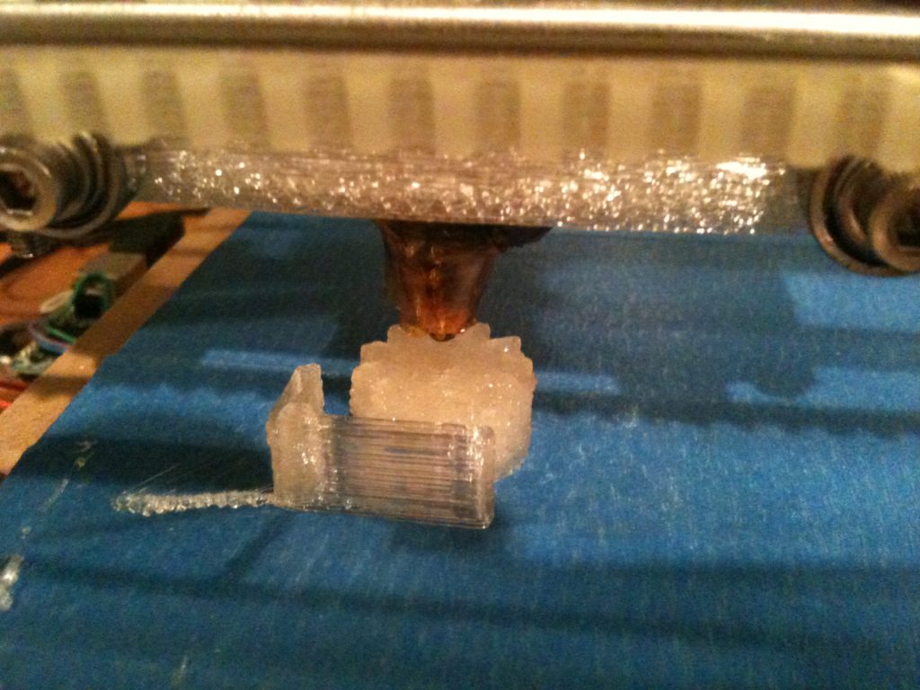
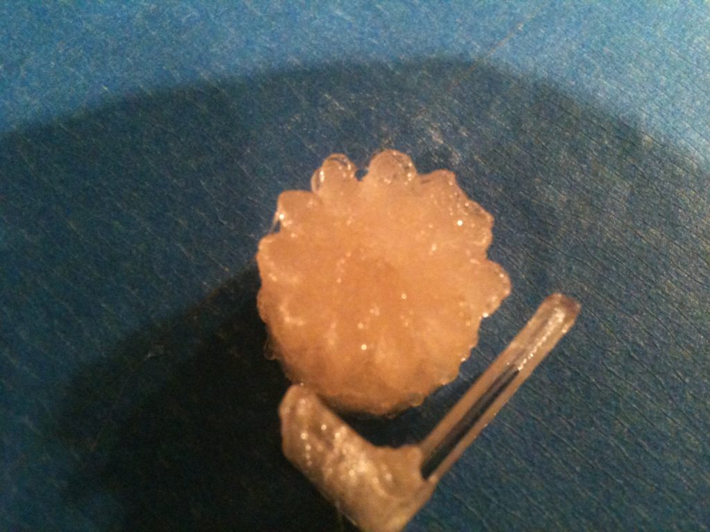
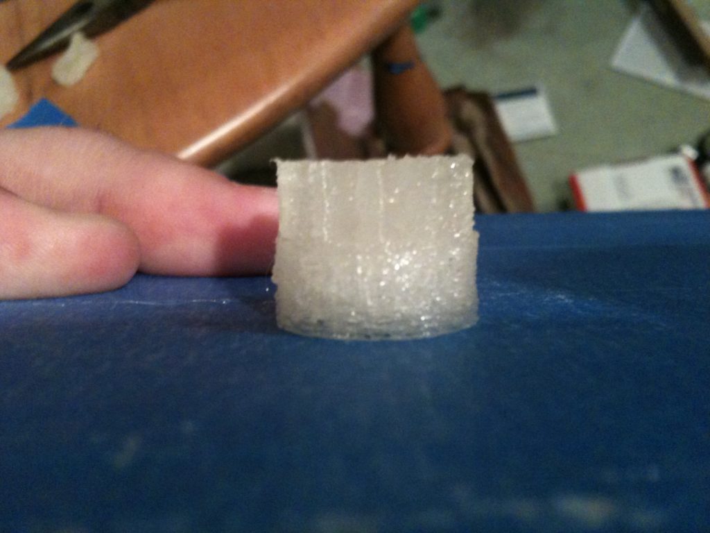
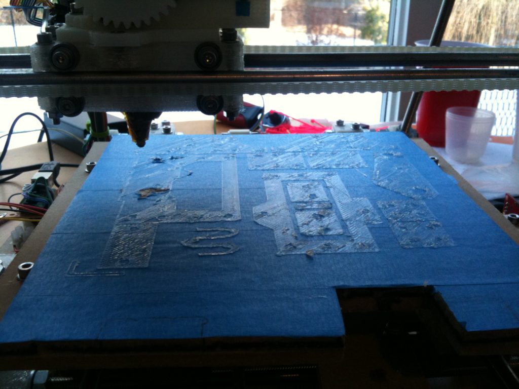
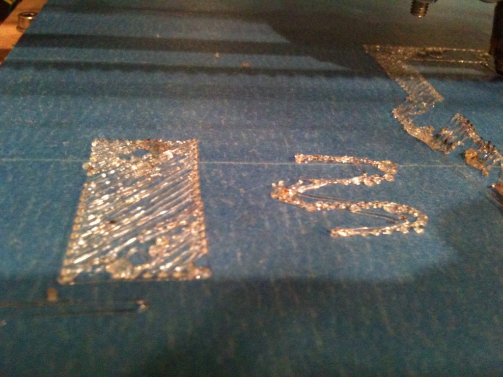
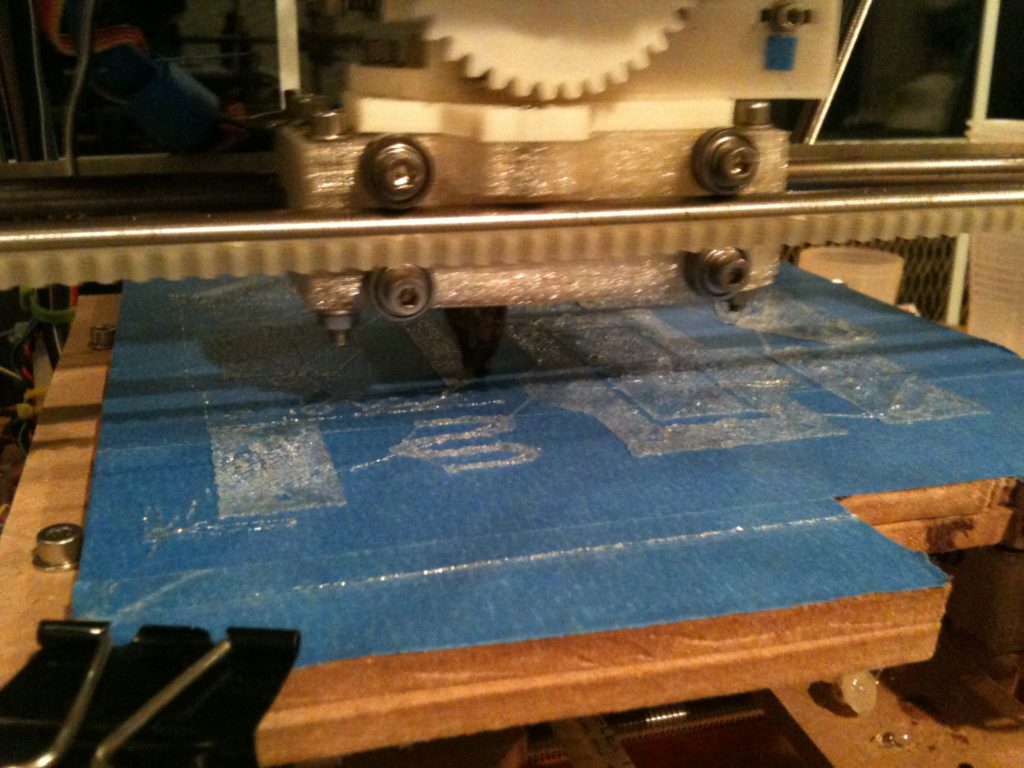
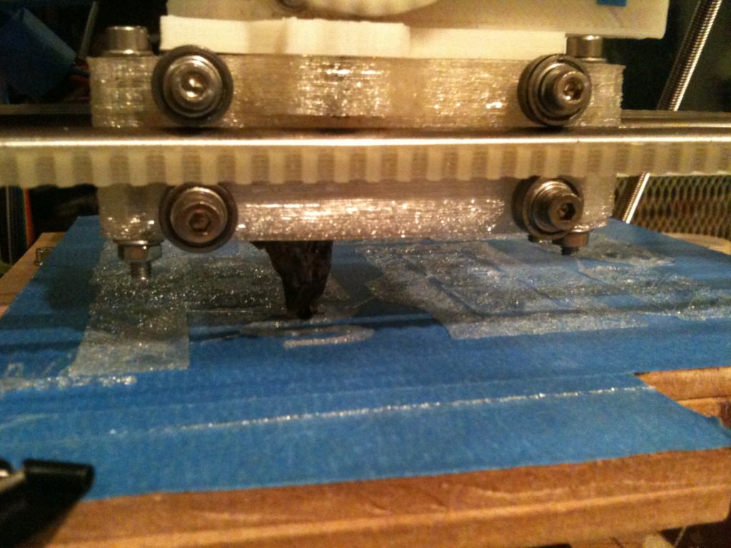
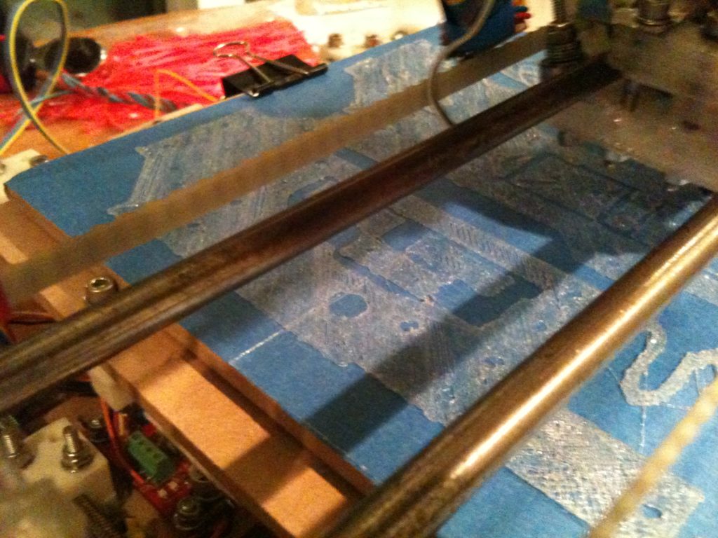
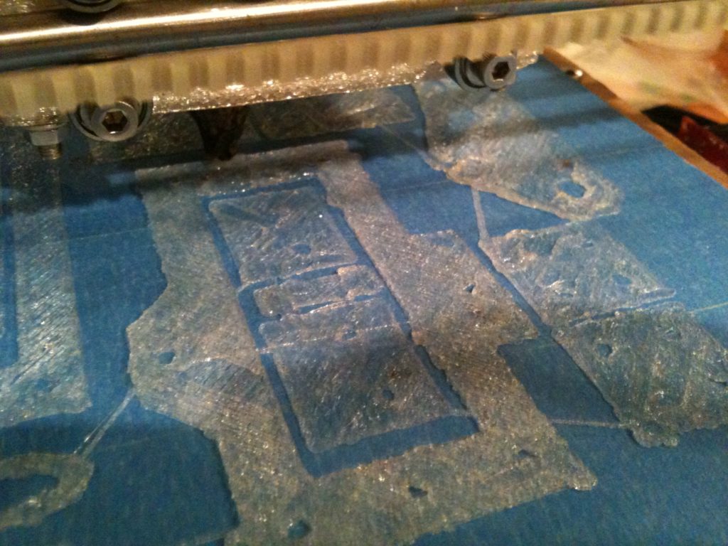
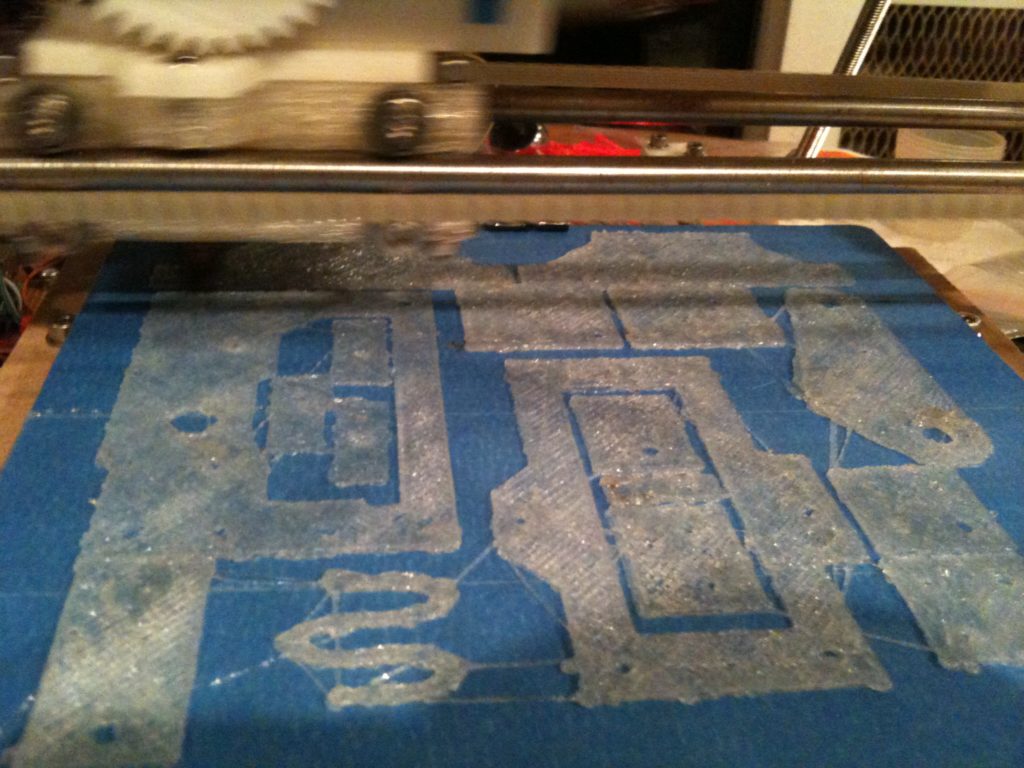
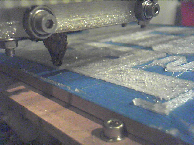
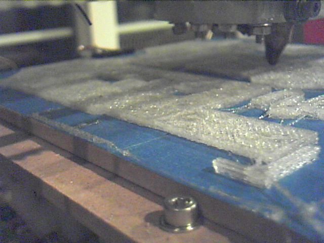
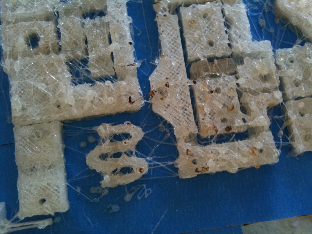
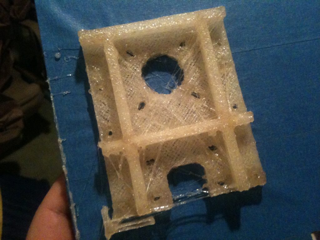
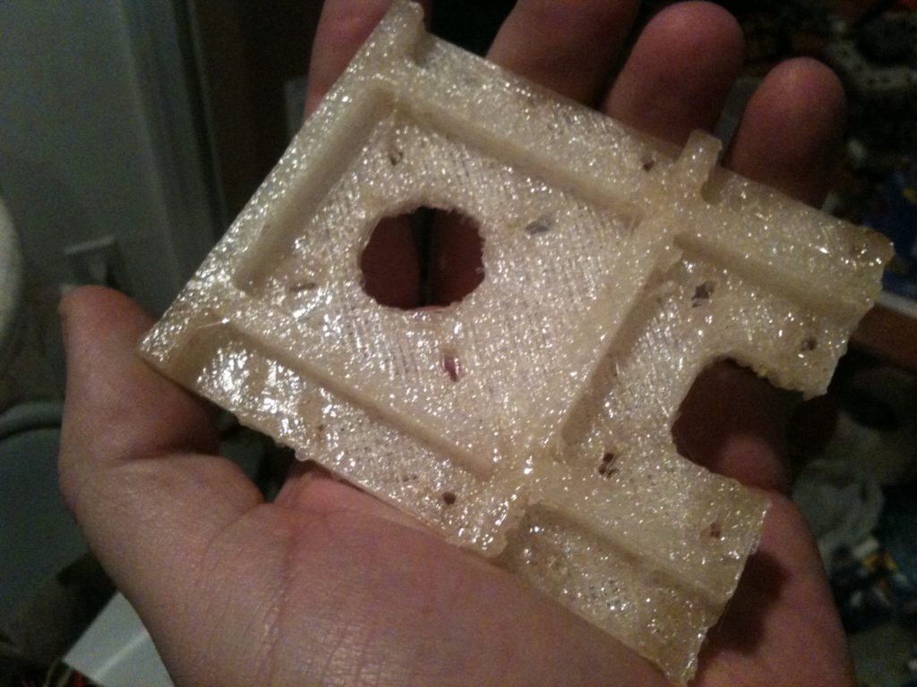
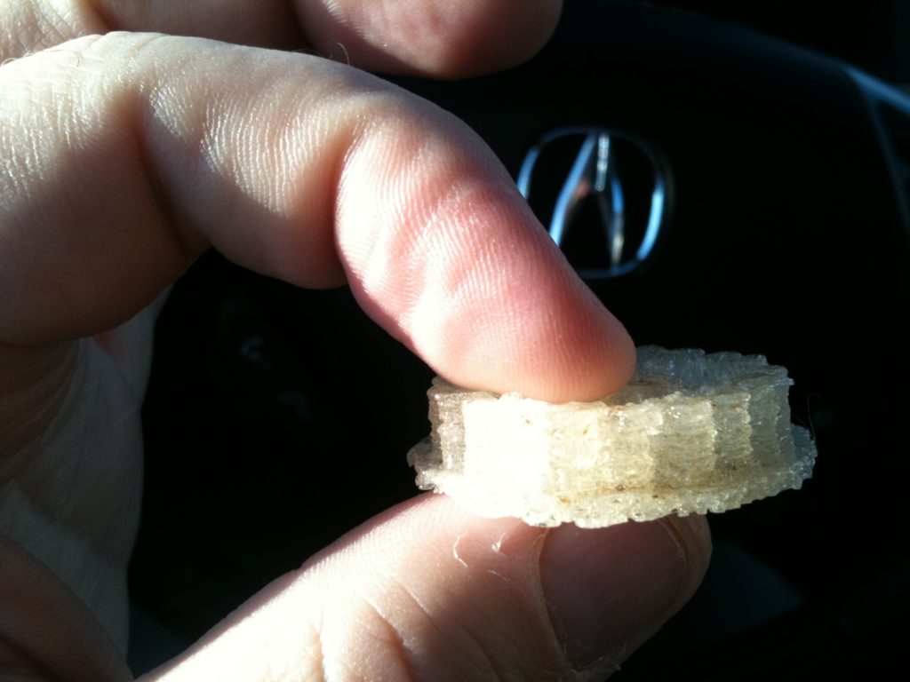
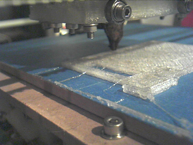
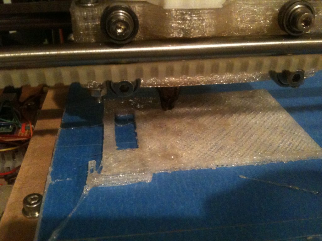
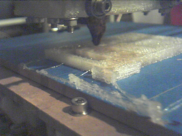
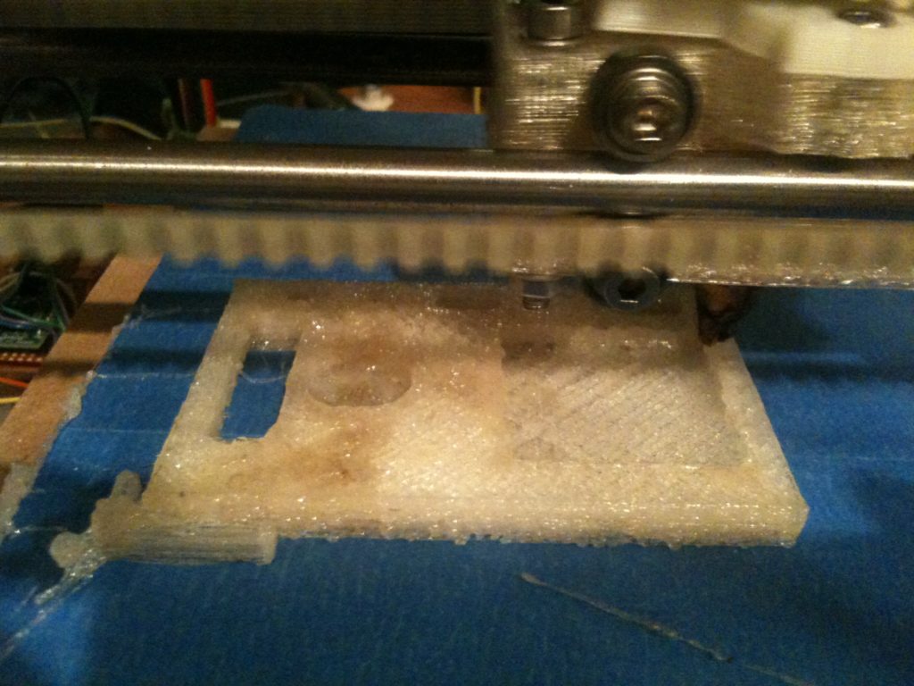
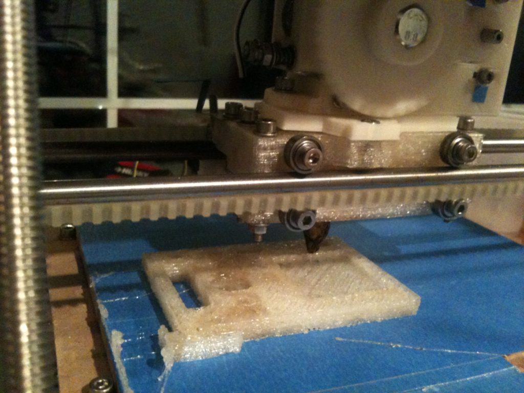
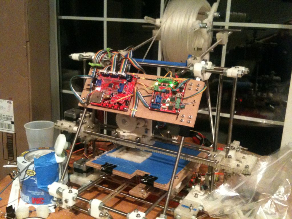
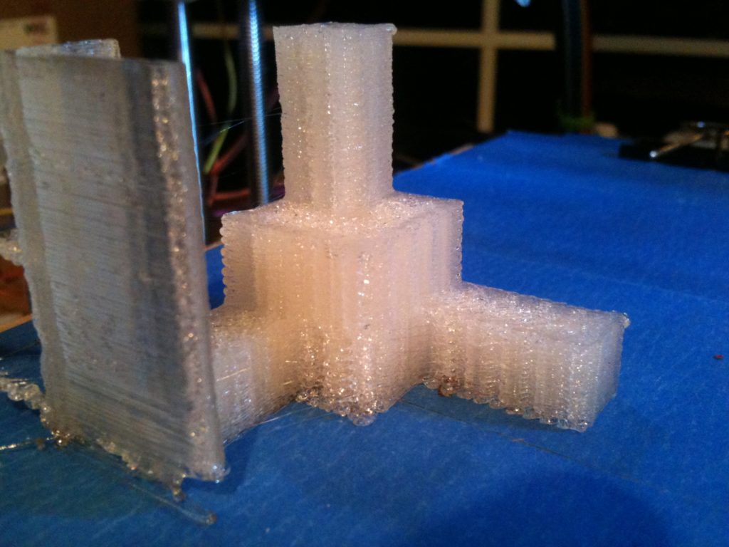
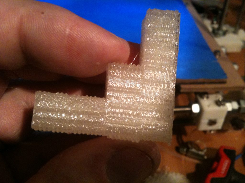
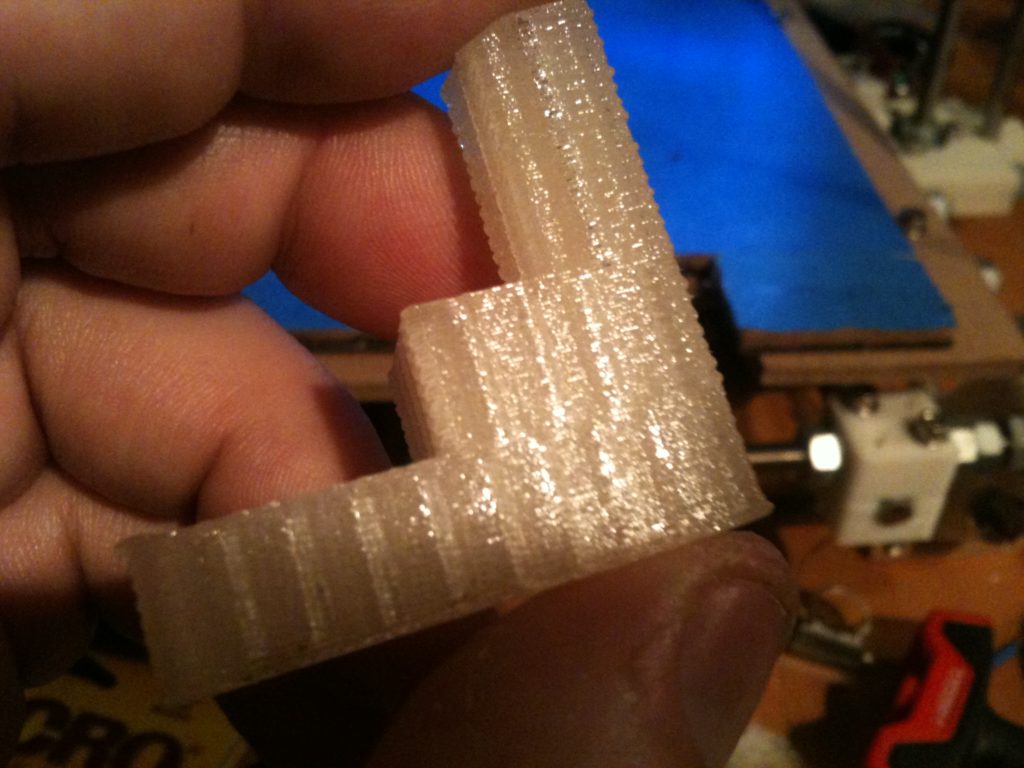
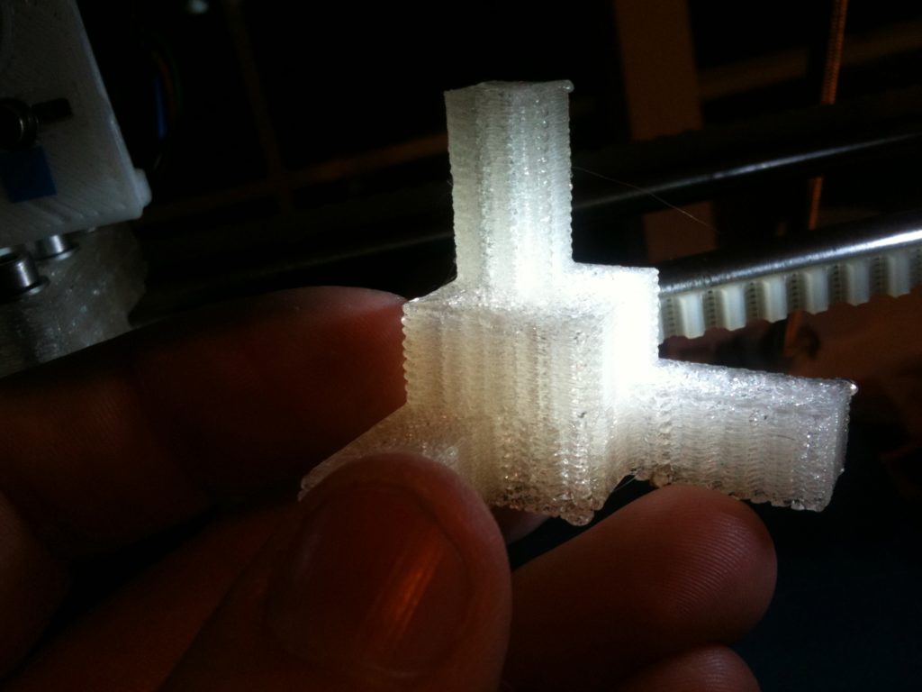
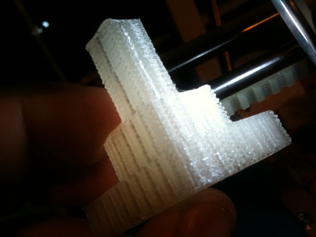
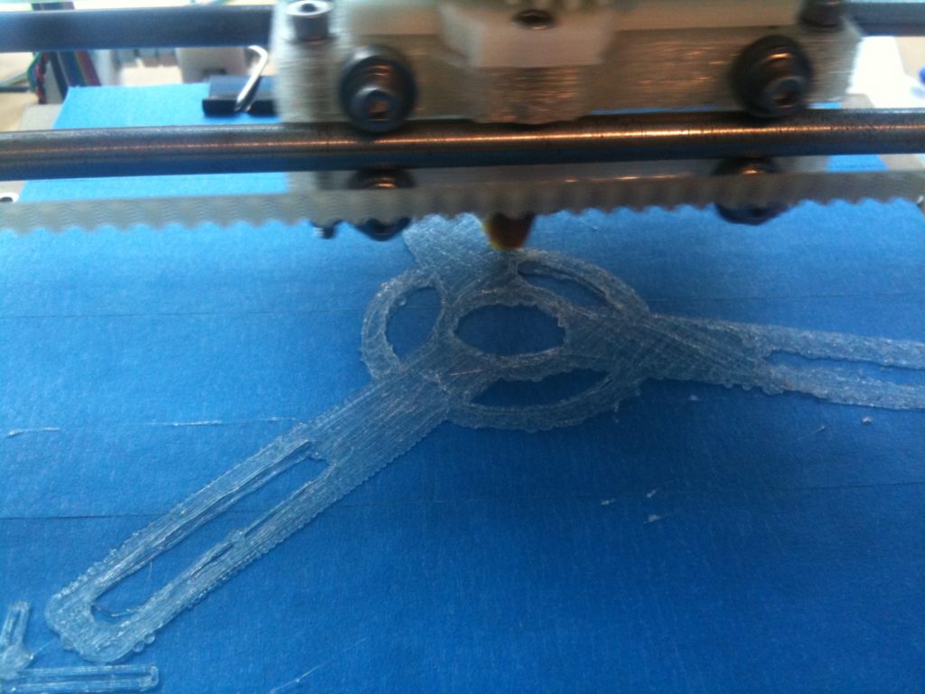
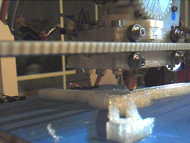
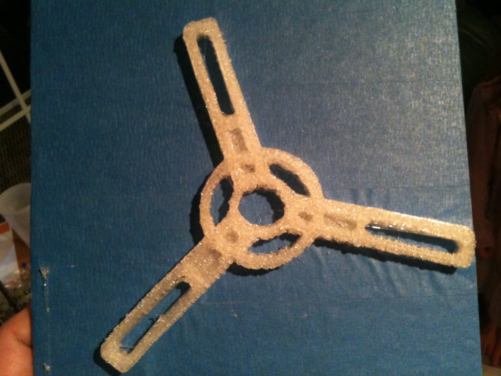
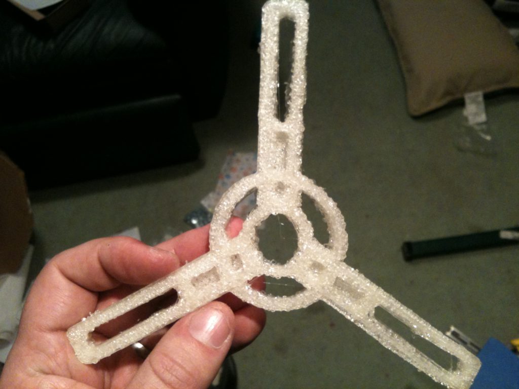
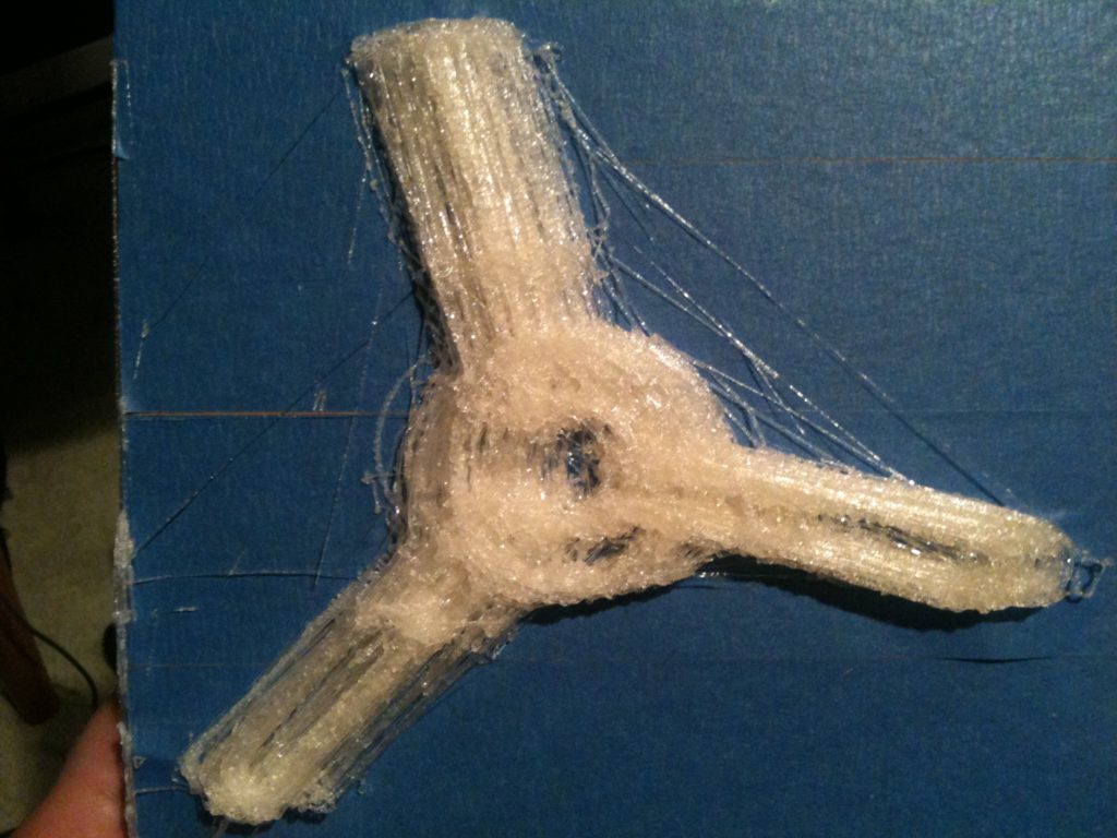
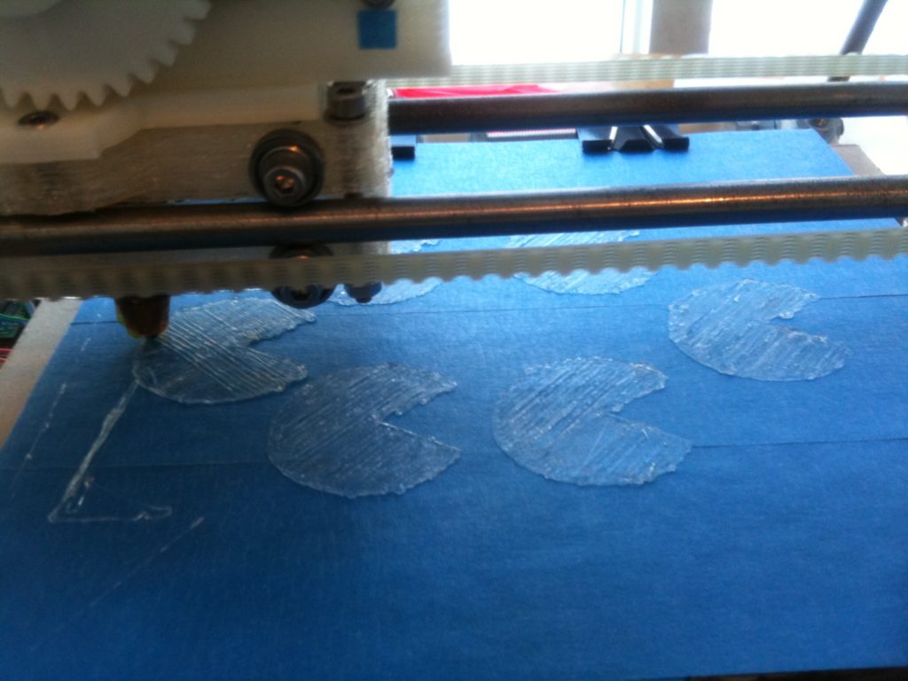
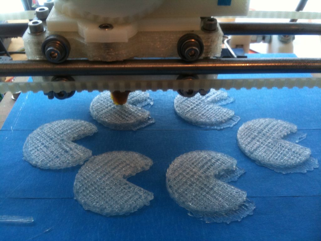
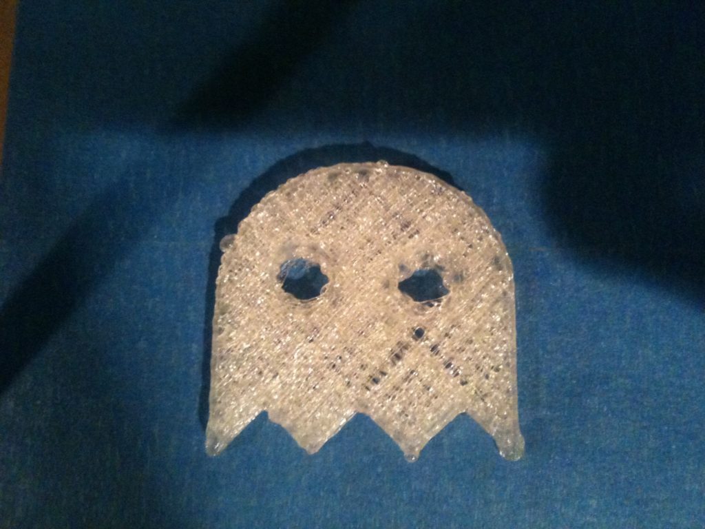
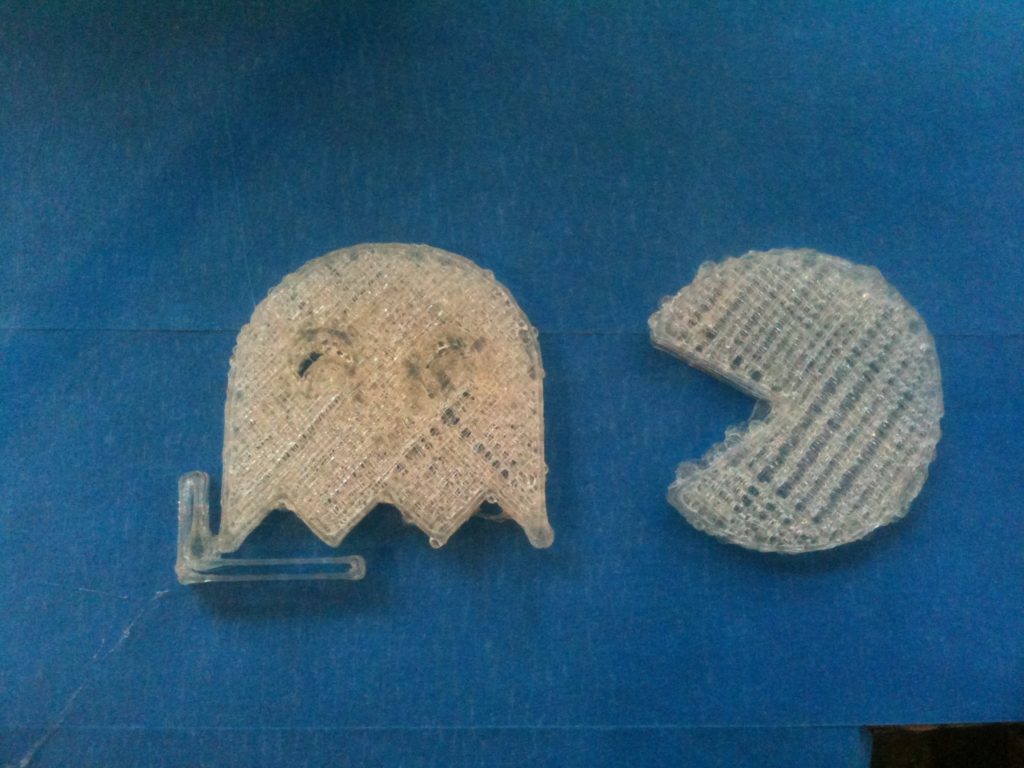
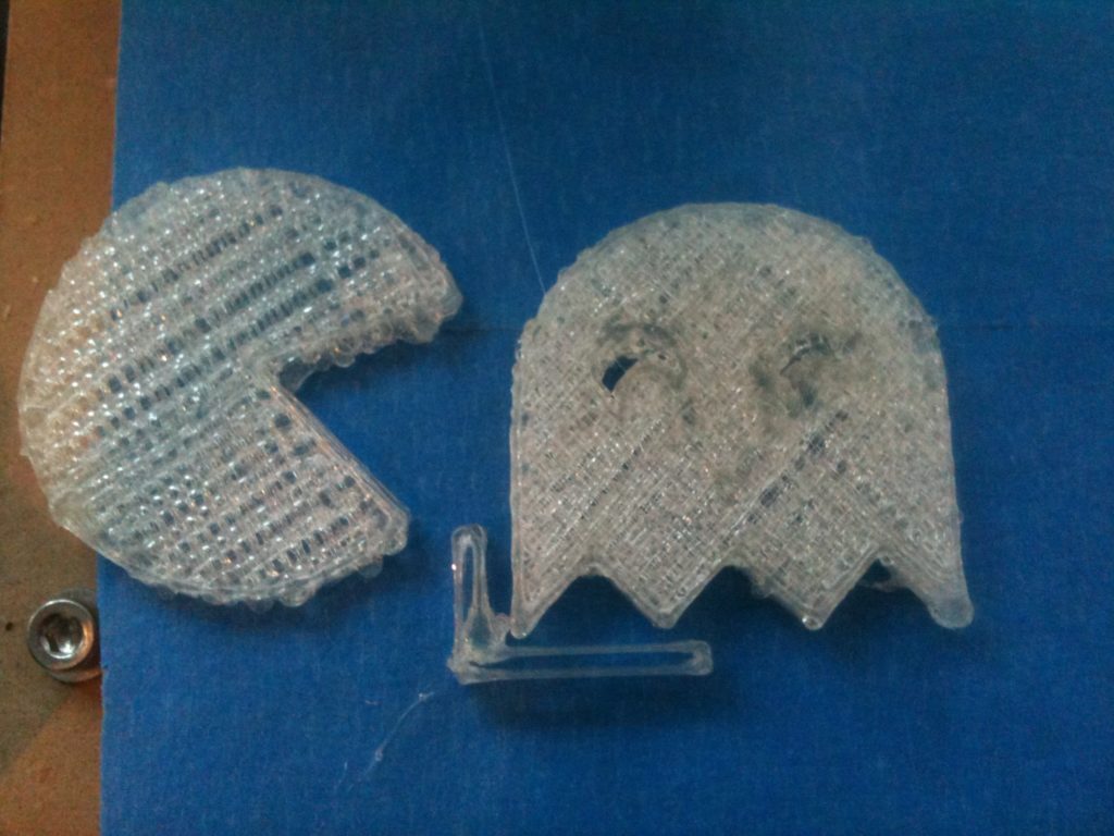
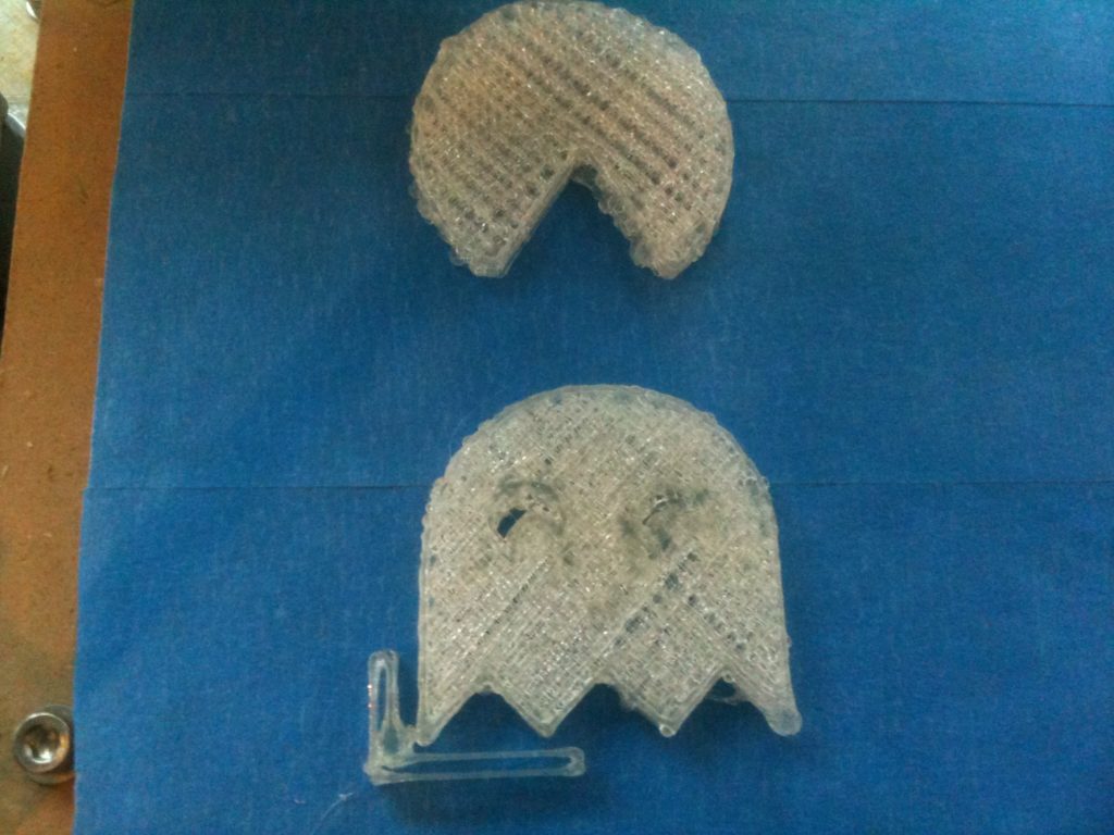
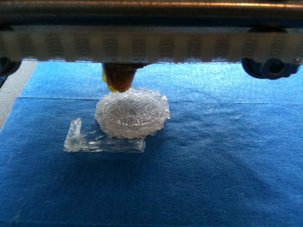
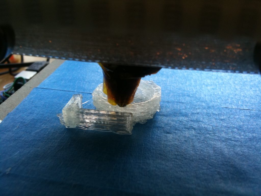
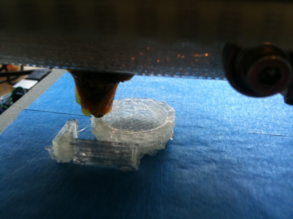
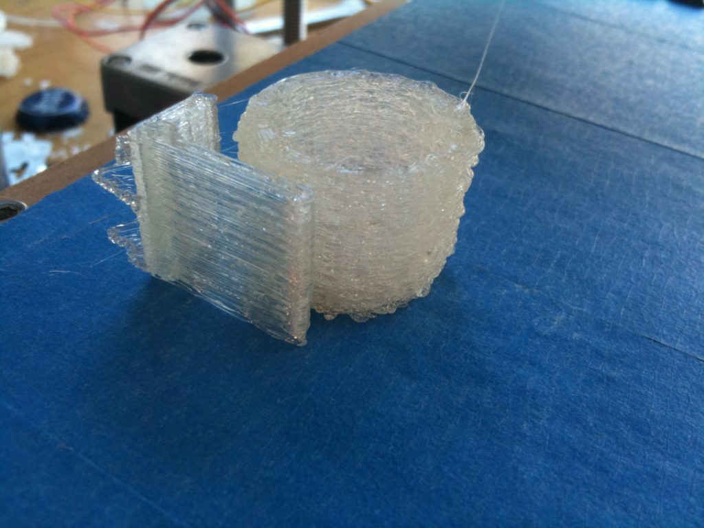
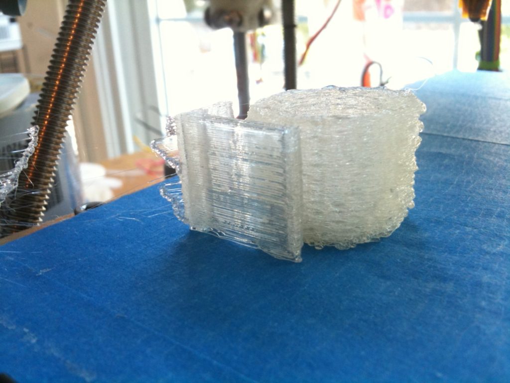
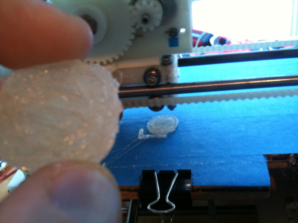
The next day, I hooked it up, and did my first print with my new heater block.
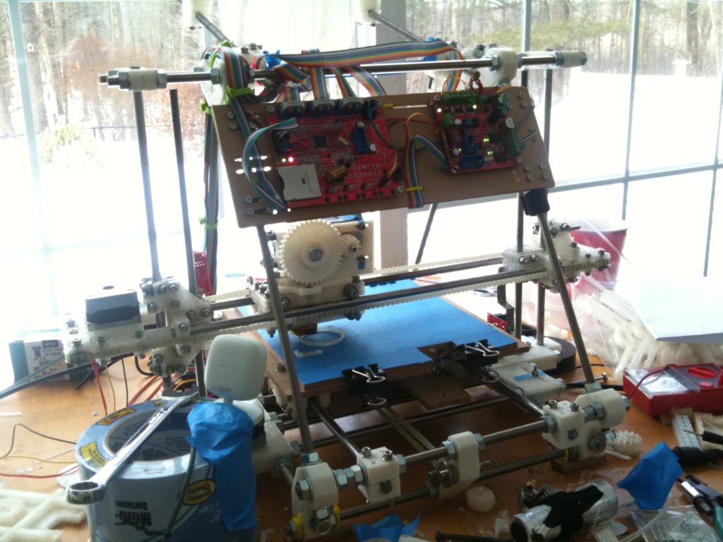
And I’ll leave you with one peaceful, uneventful video I took of it printing that afternoon, and end this post on that happy note. My printer was printing nicely, everything was going well. What a beautiful machine.
Stay tuned for part 4 of ?
