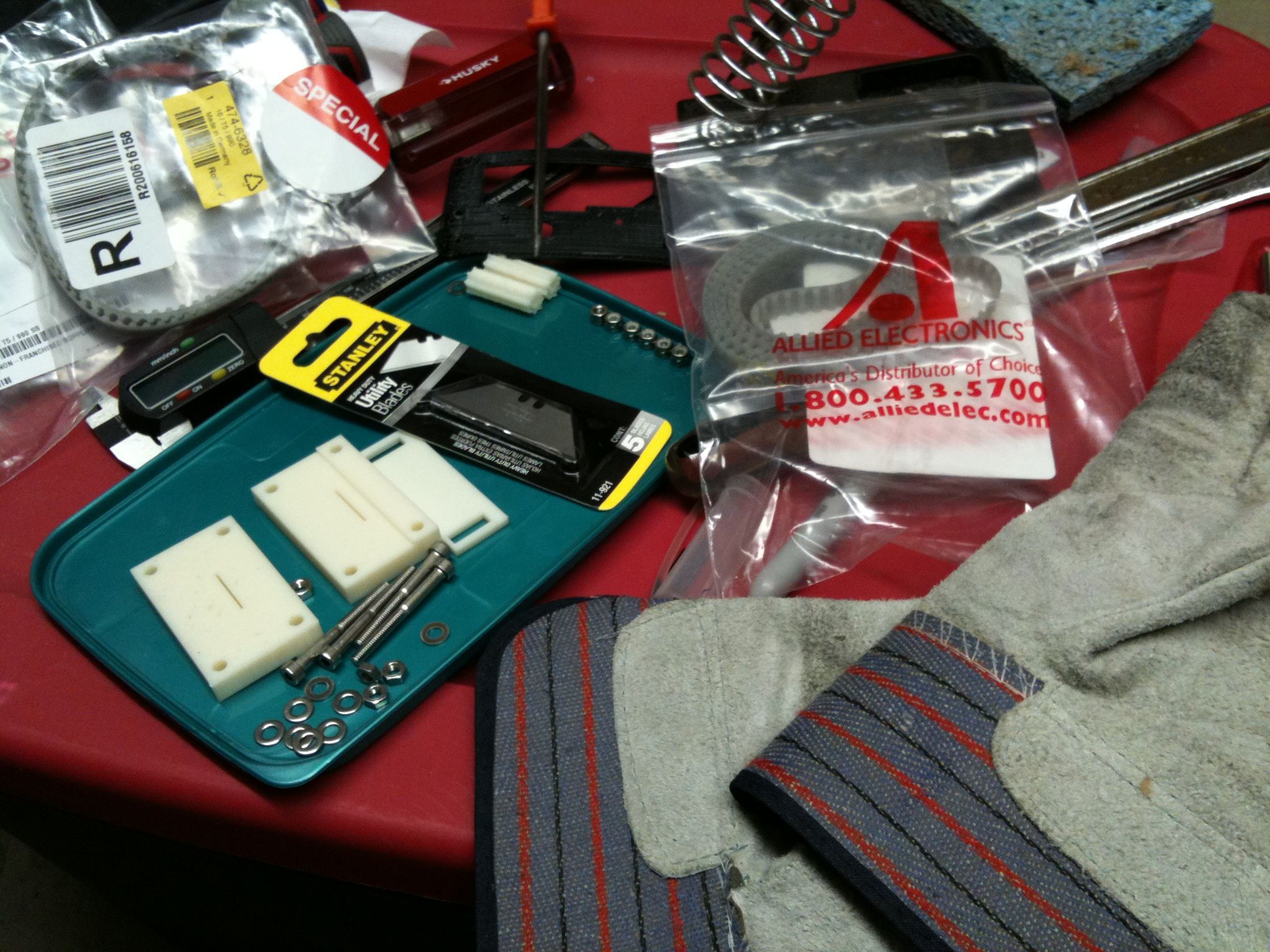
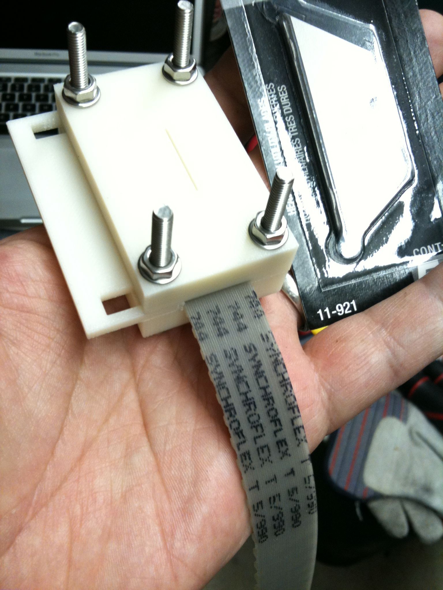
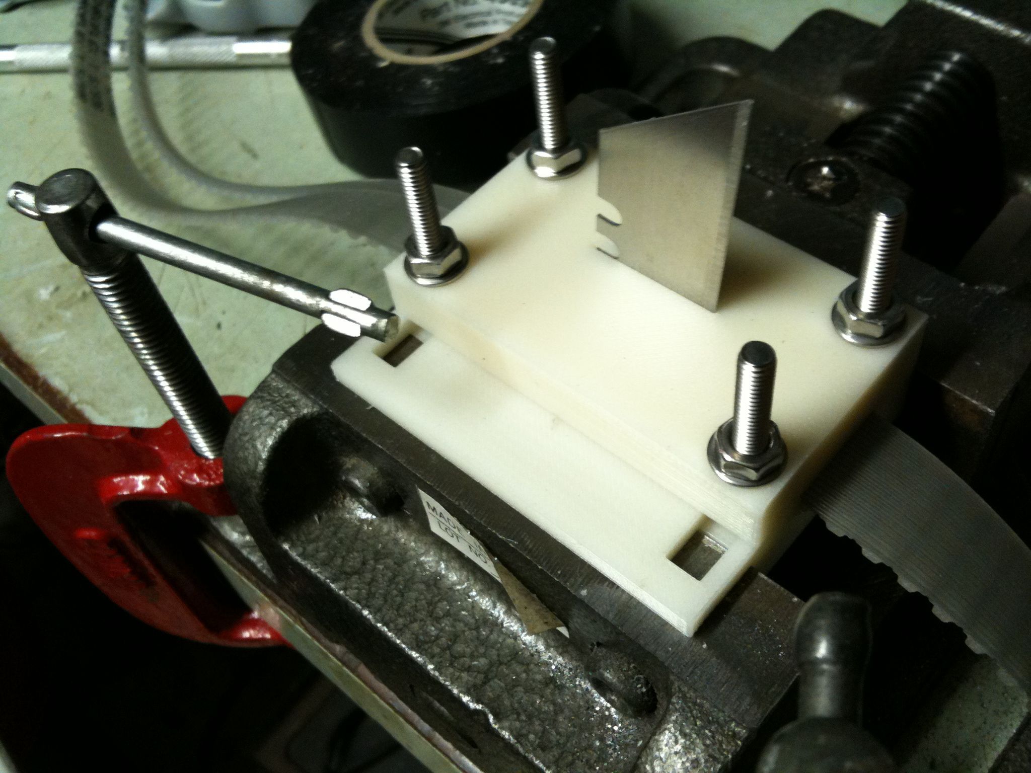
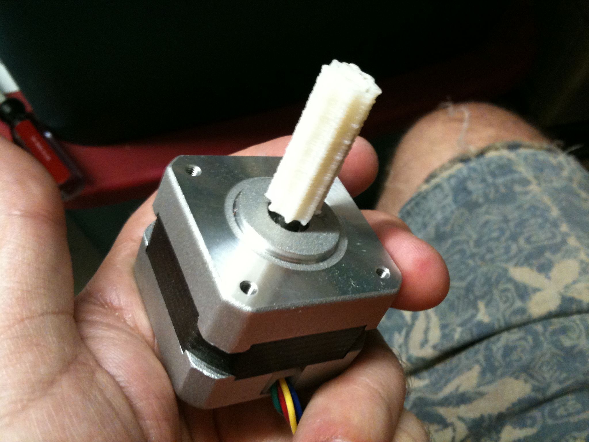
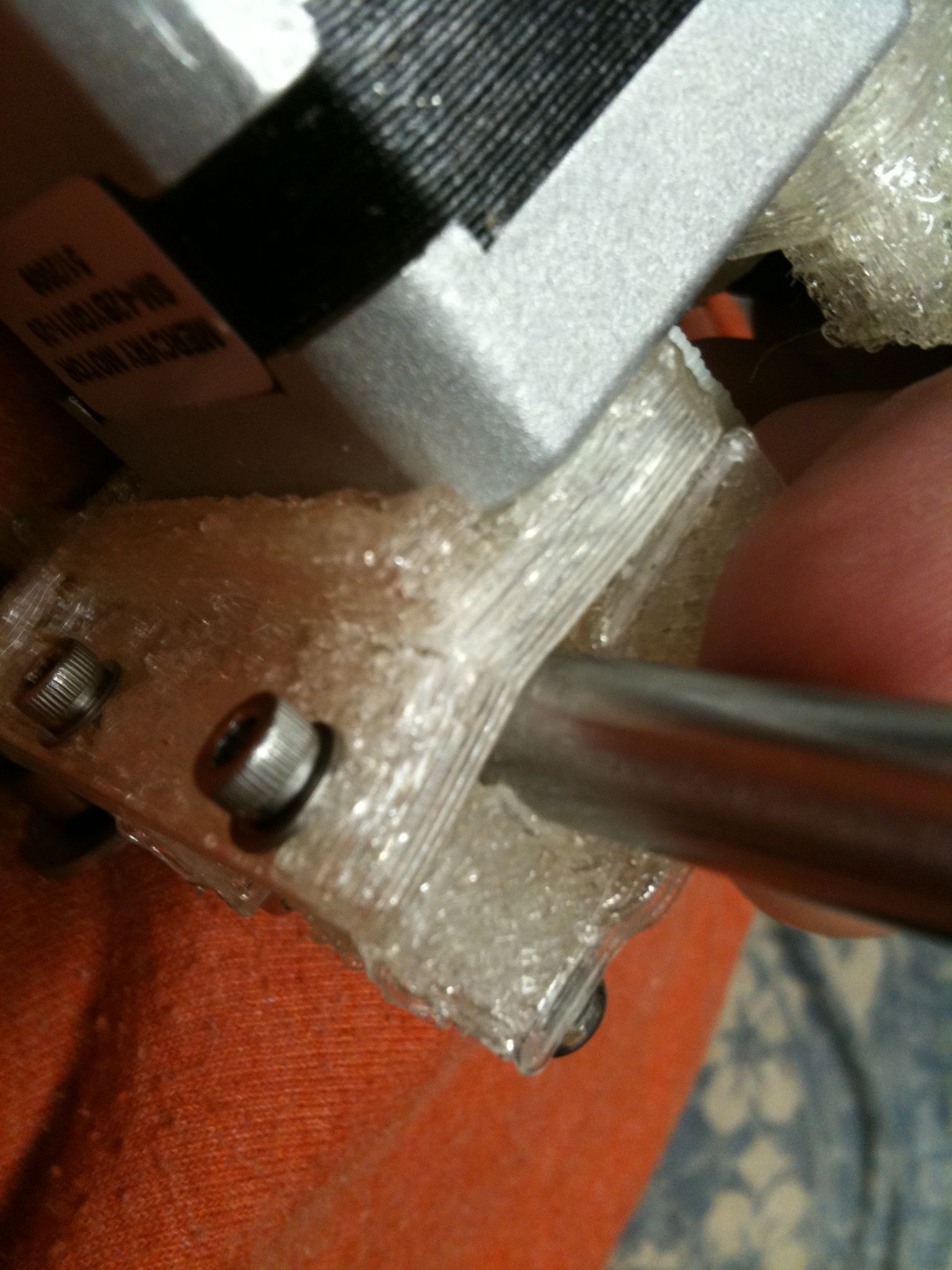
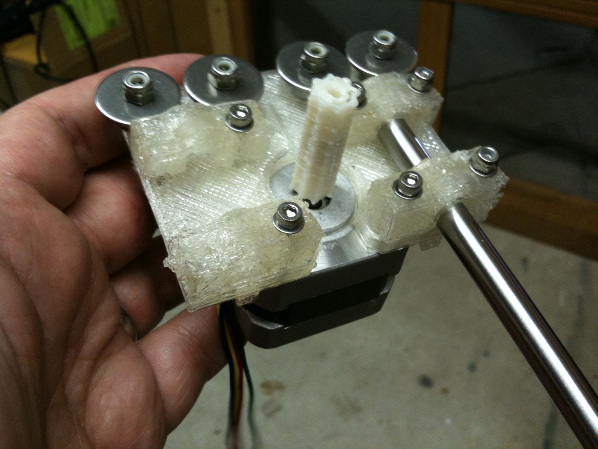
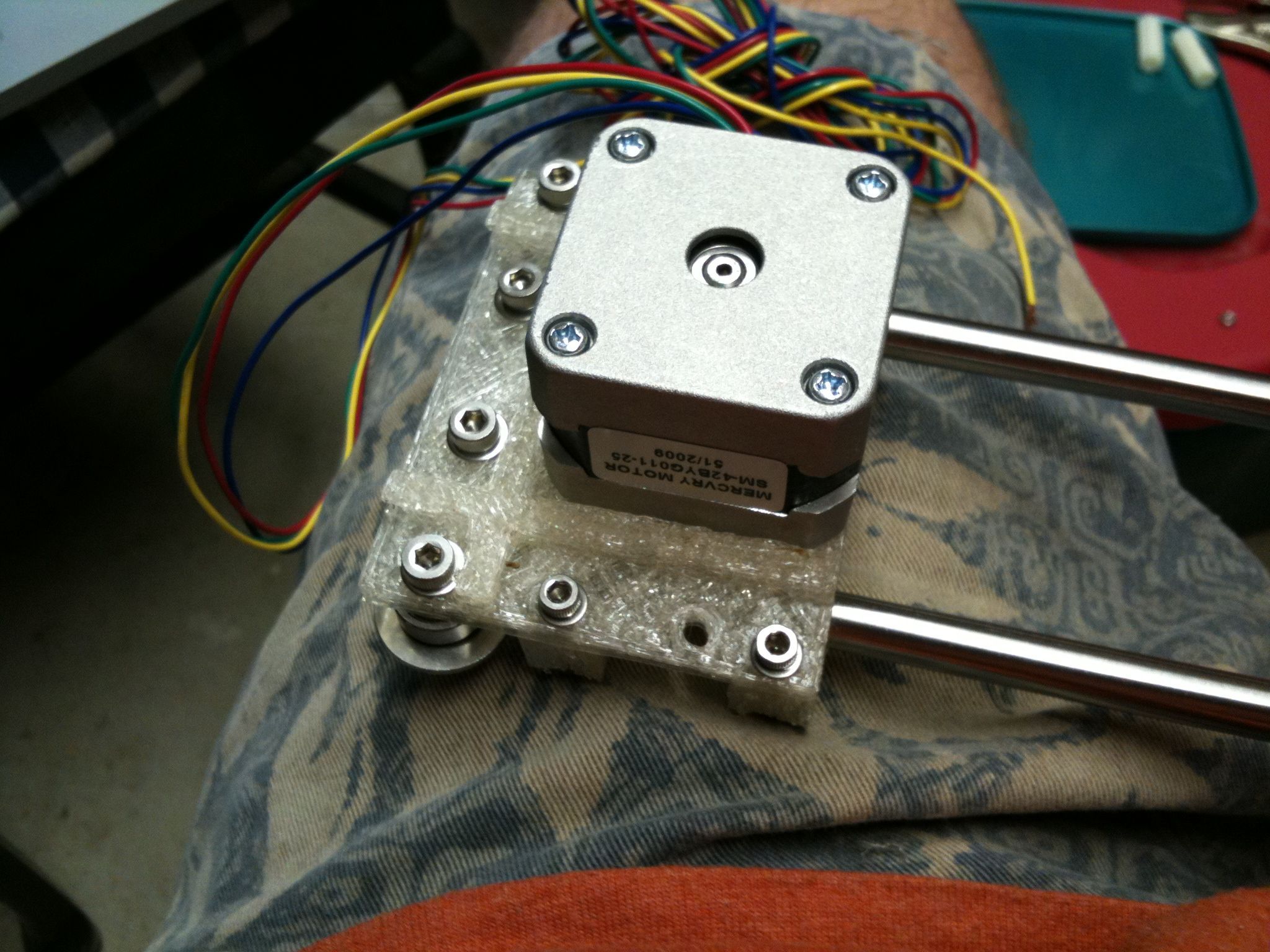
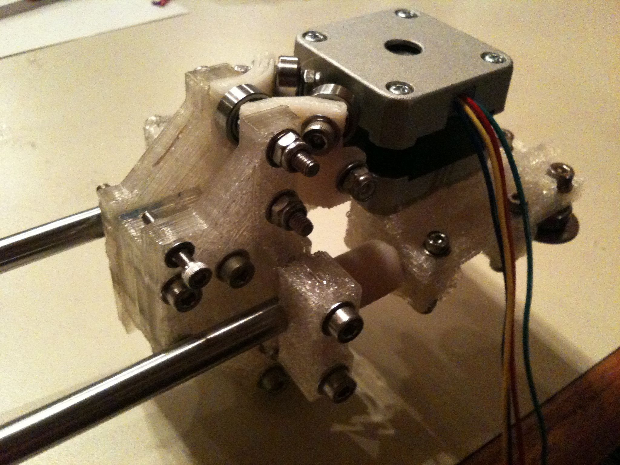
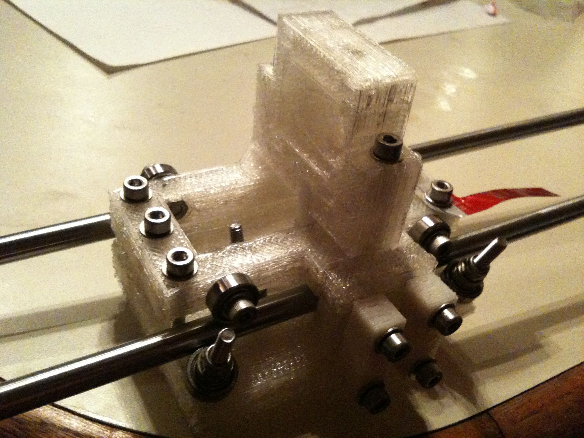
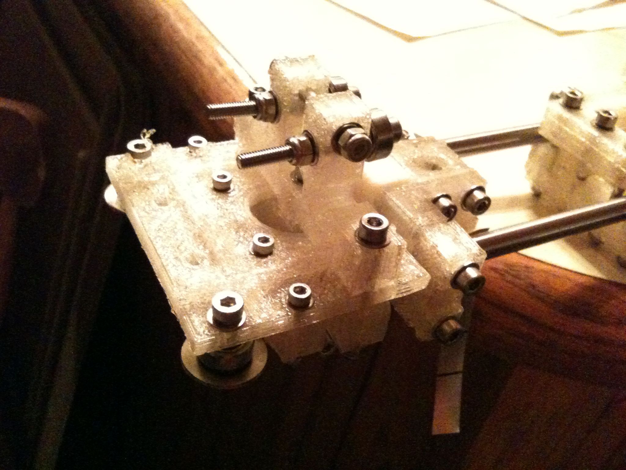
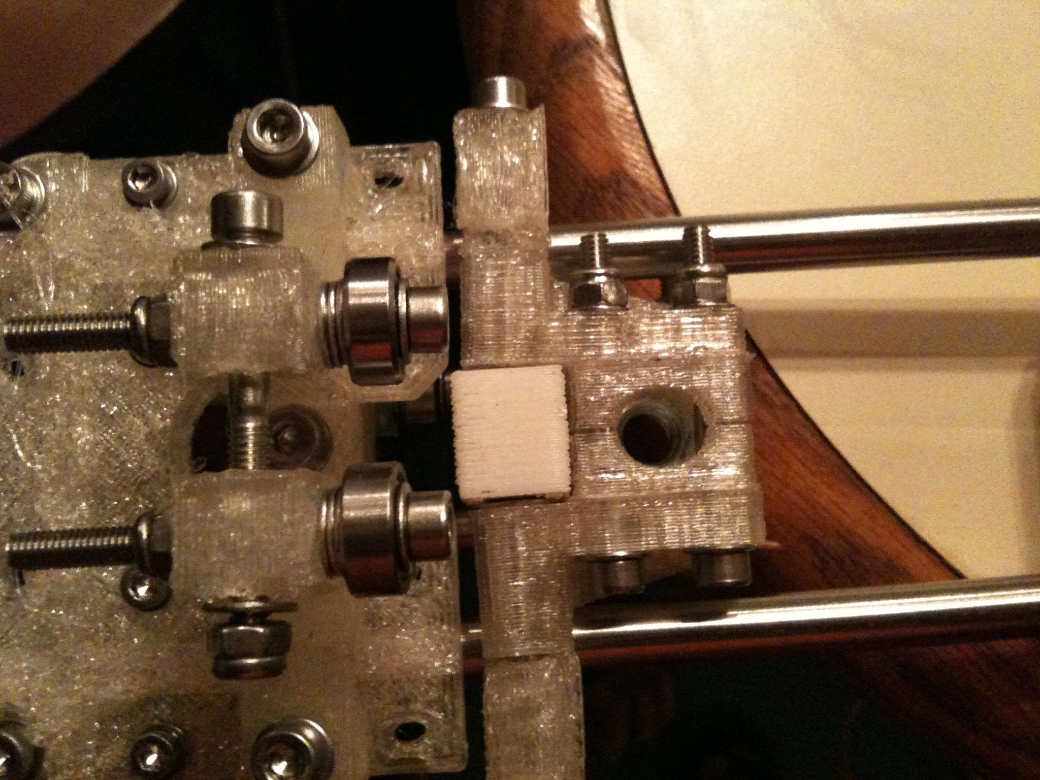
Ok, I moved the rest of the pictures off of my wife’s phone, so here’s part 2 of the progress from this past weekend. Despite the fact that these are large 9-megapixel pictures, they should all look much smaller than normal since I’m uploading them via the web, so I’m able to use the thumbnail feature of wordpress. Click them for stunning detail. 🙂 (actually it looks like you have to click twice to get the full resolution.. me no like..)
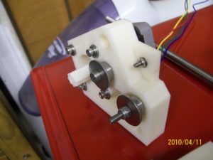
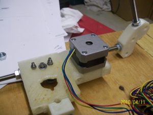
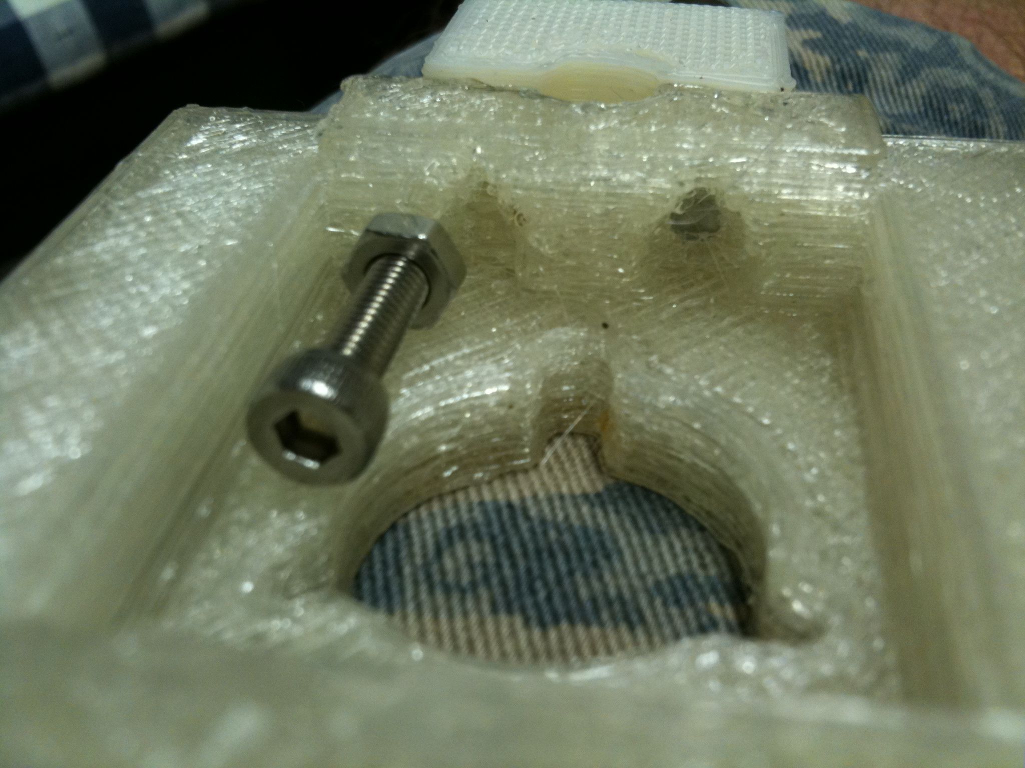
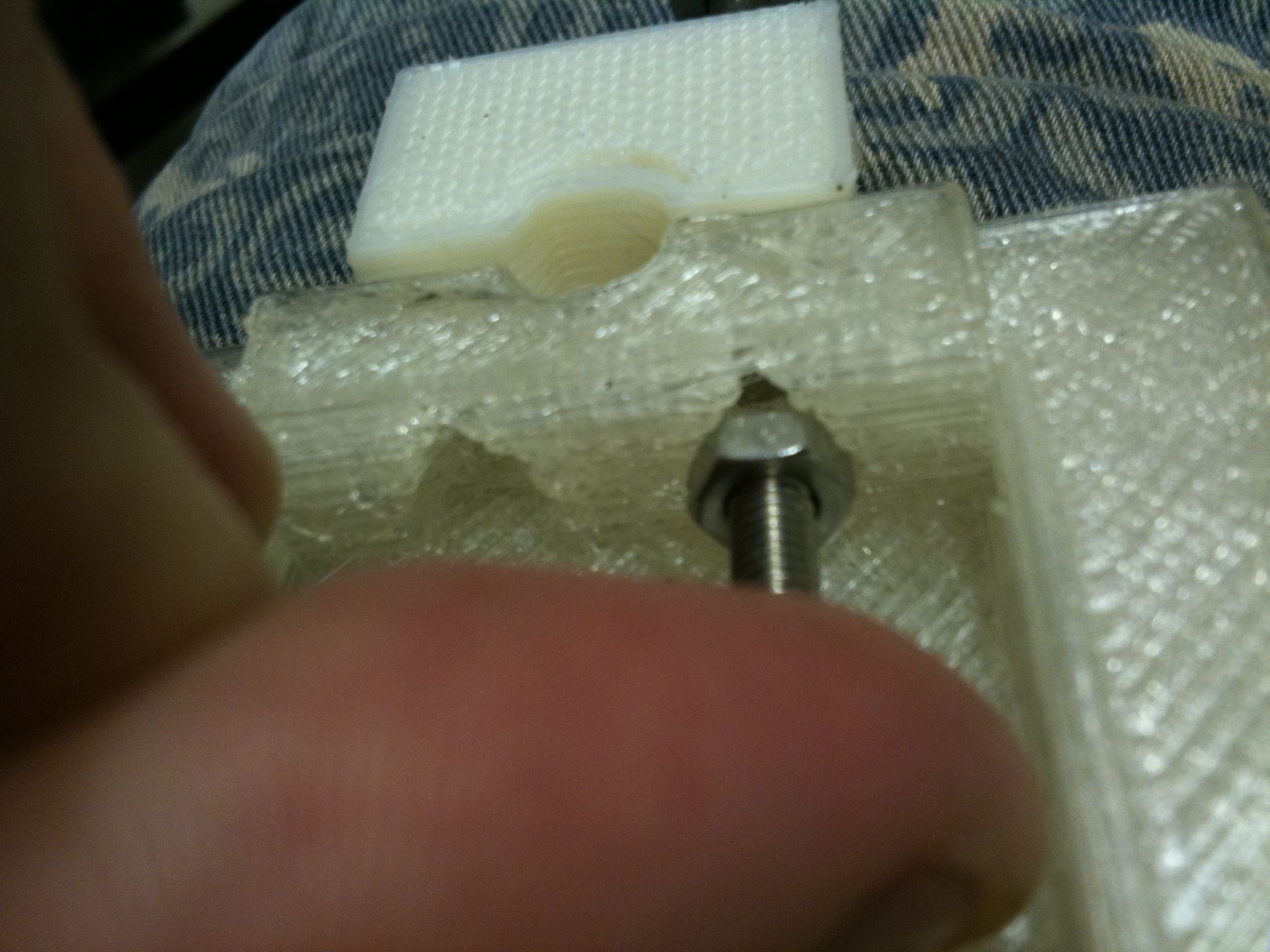
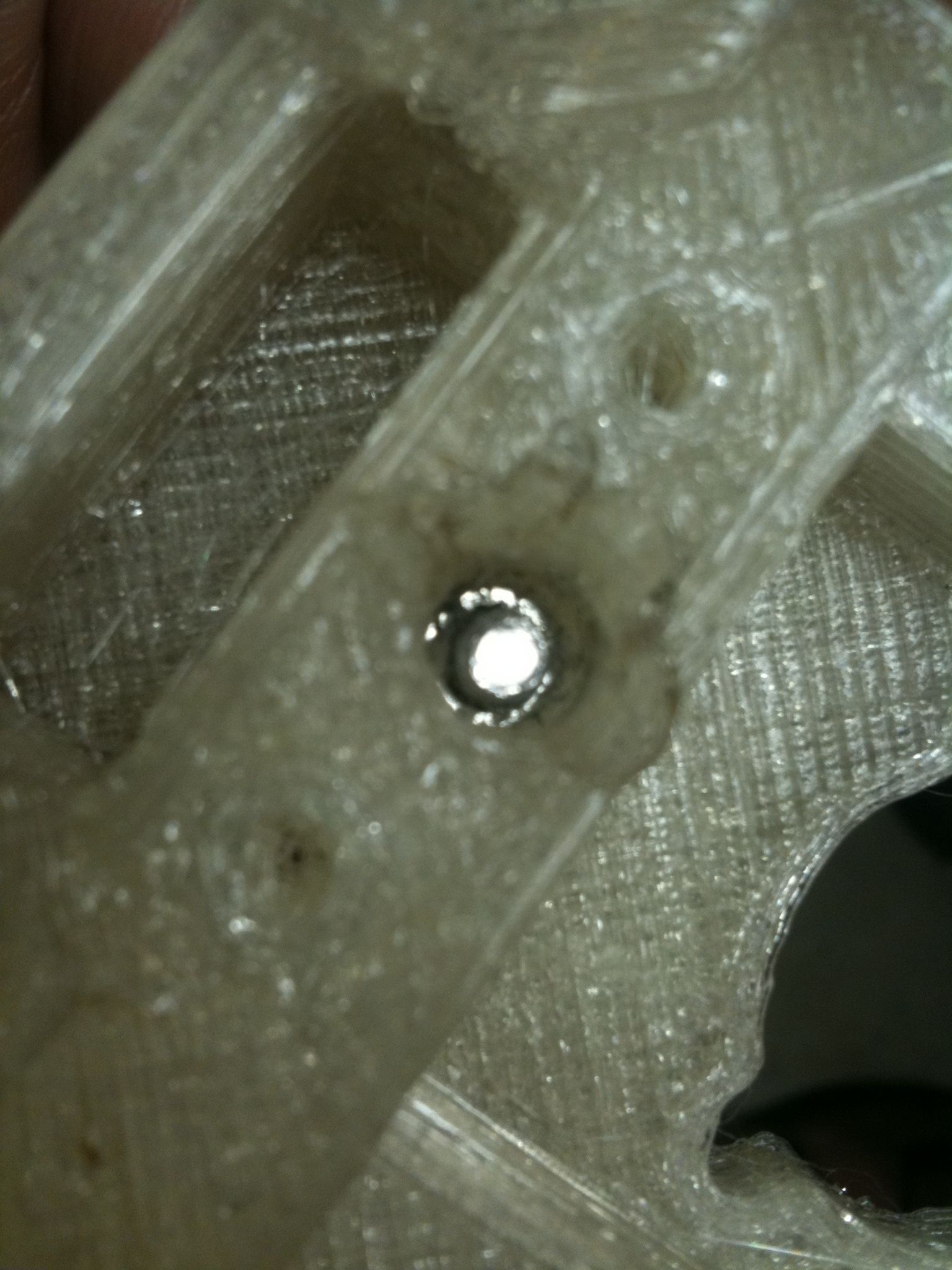
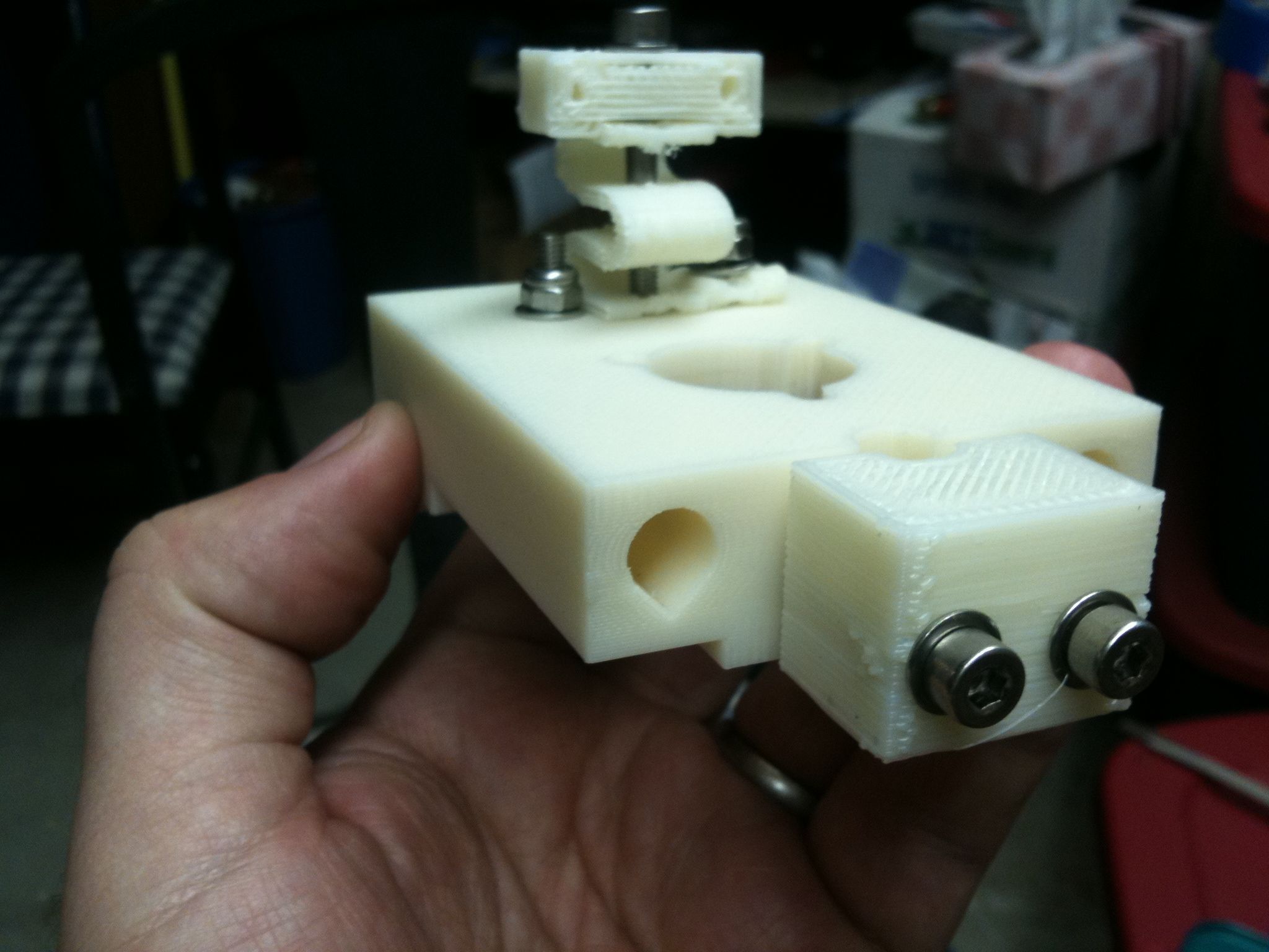
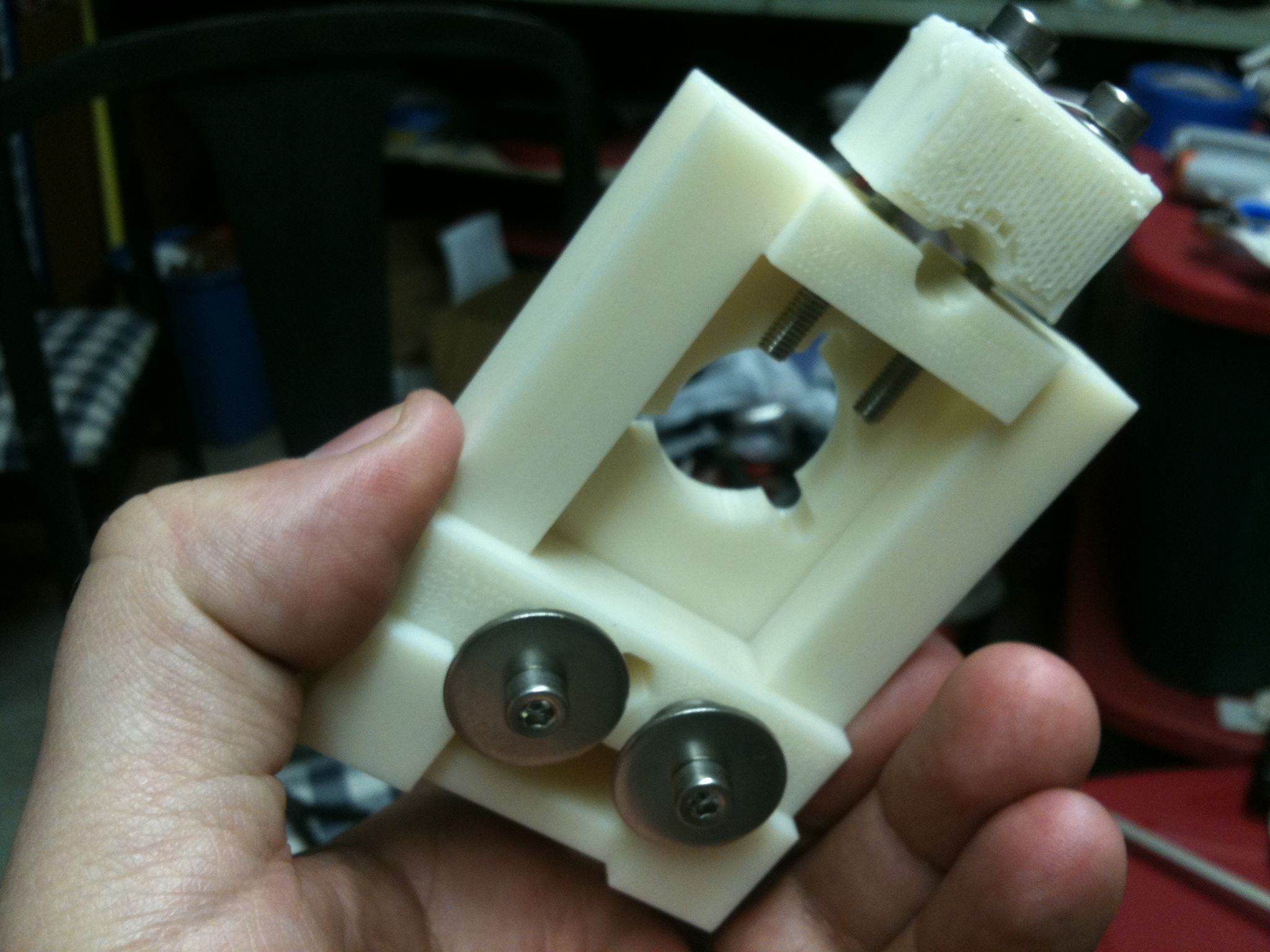
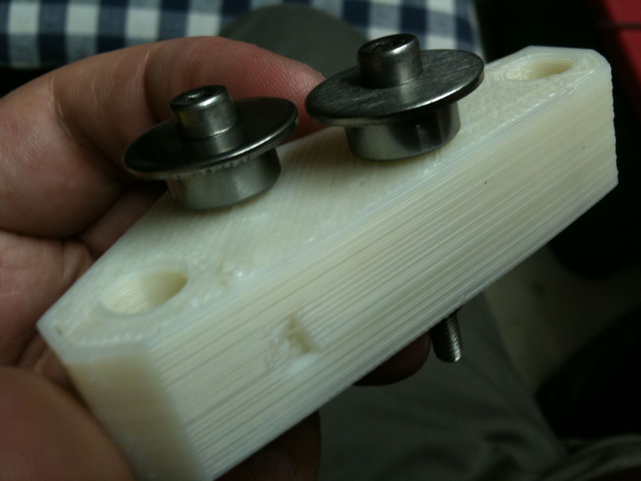
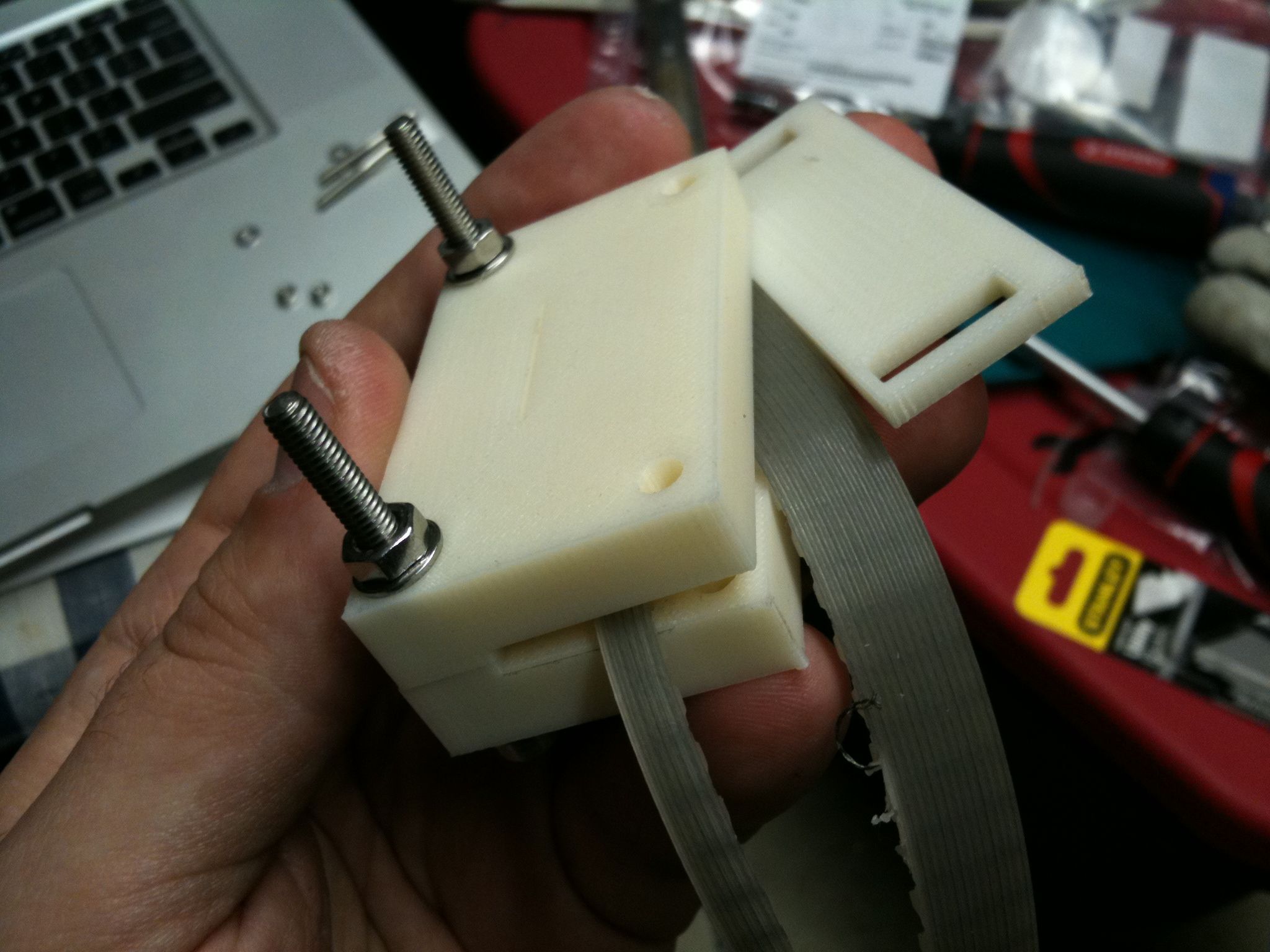
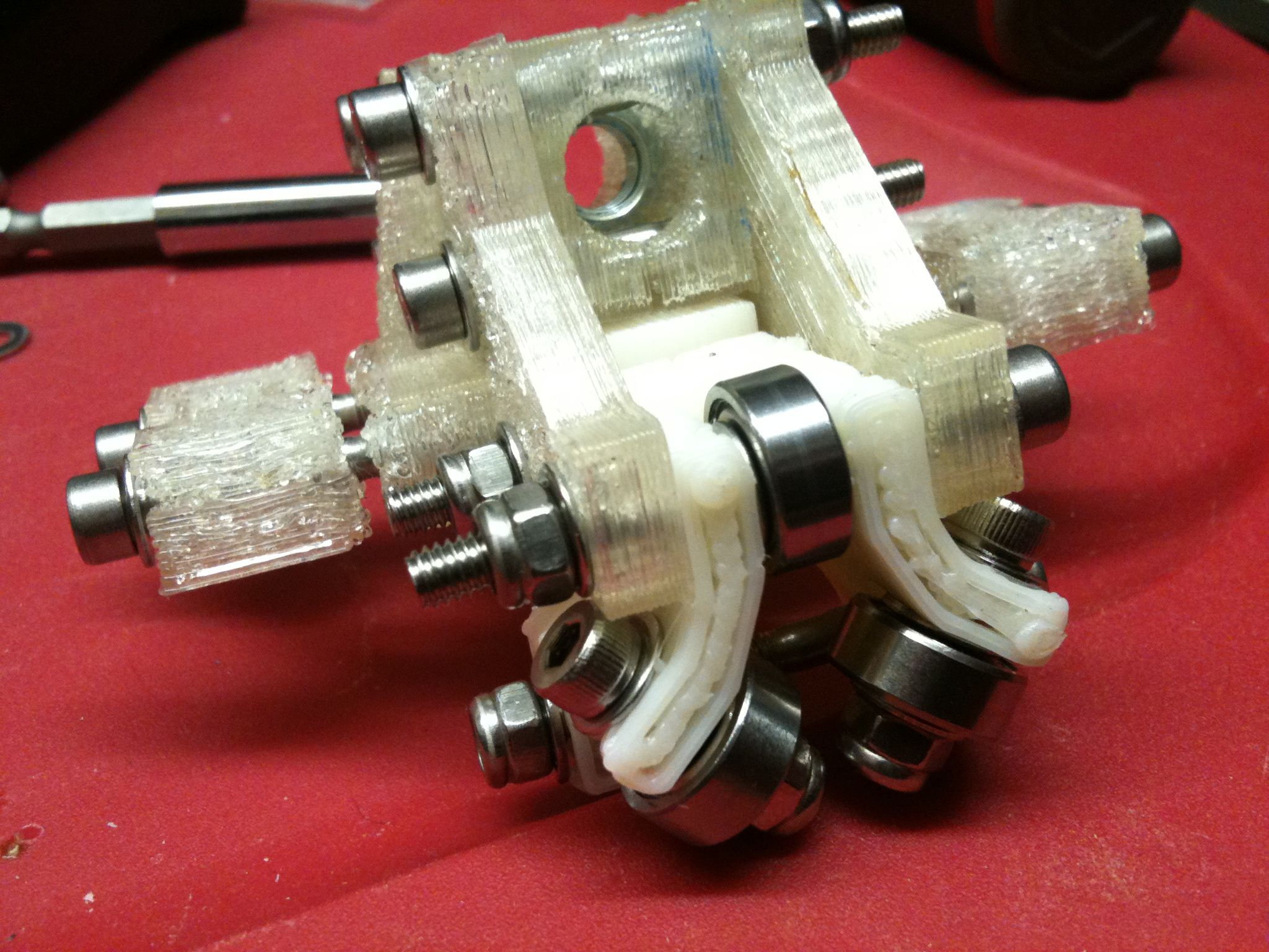
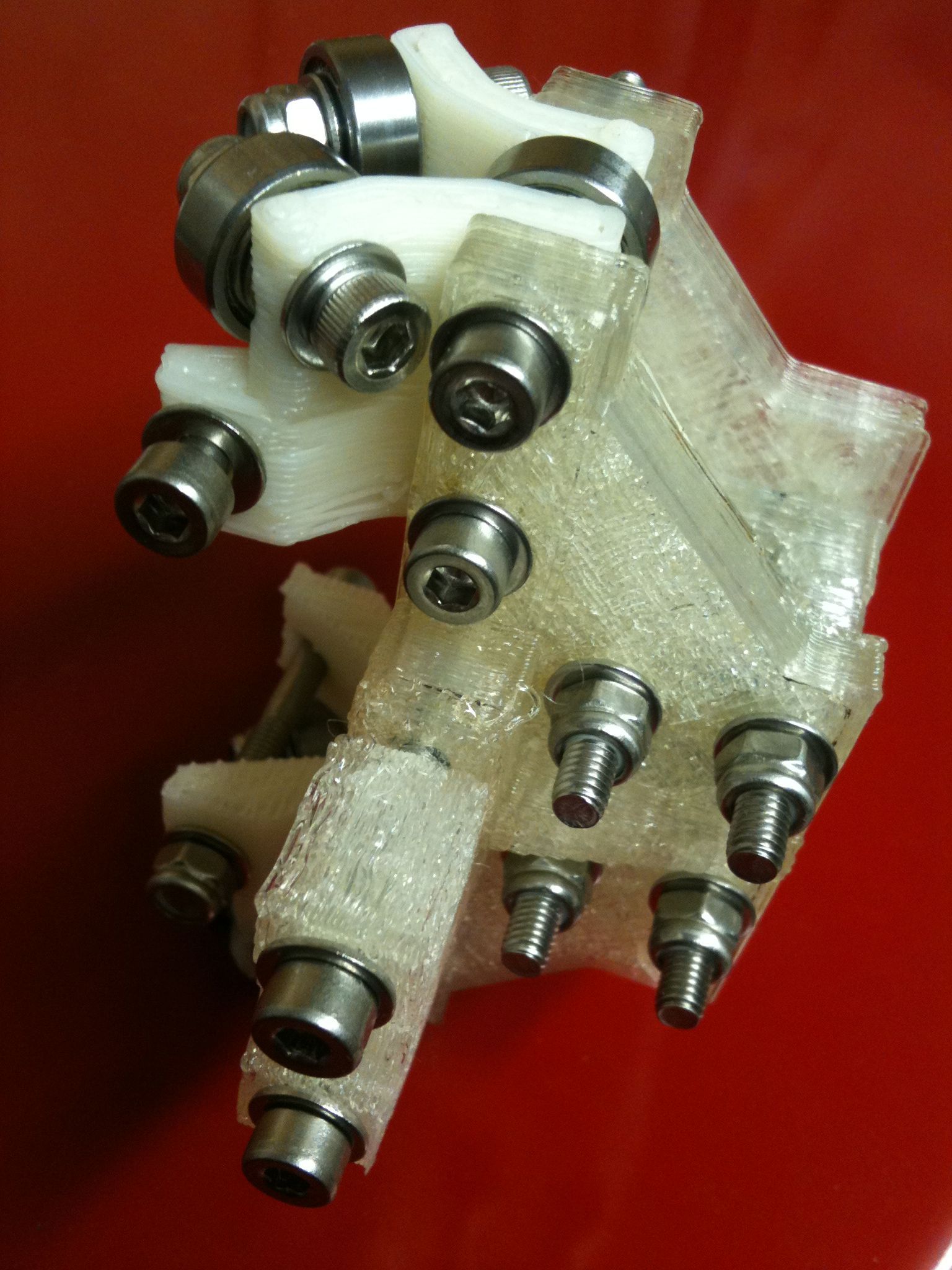
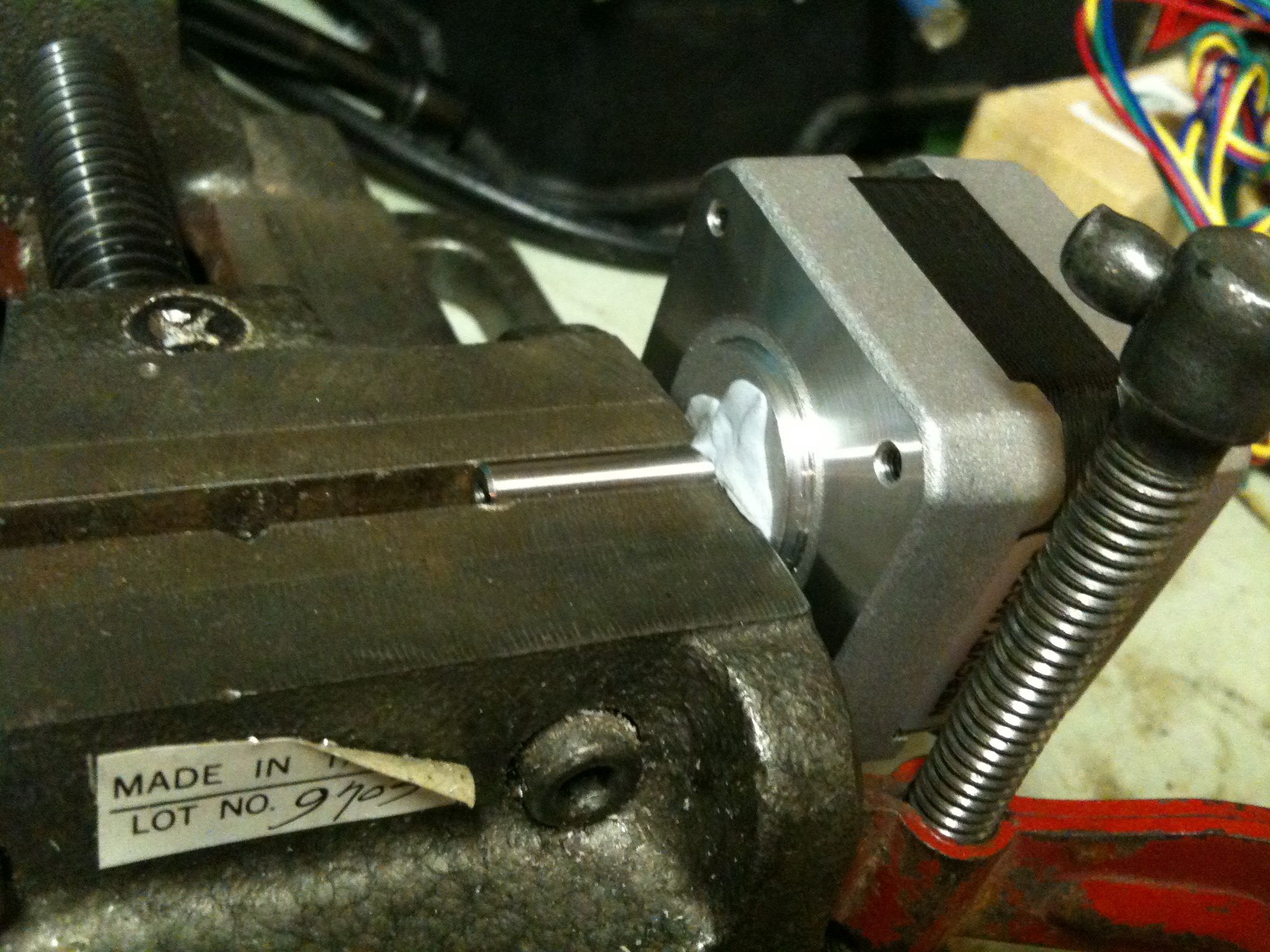
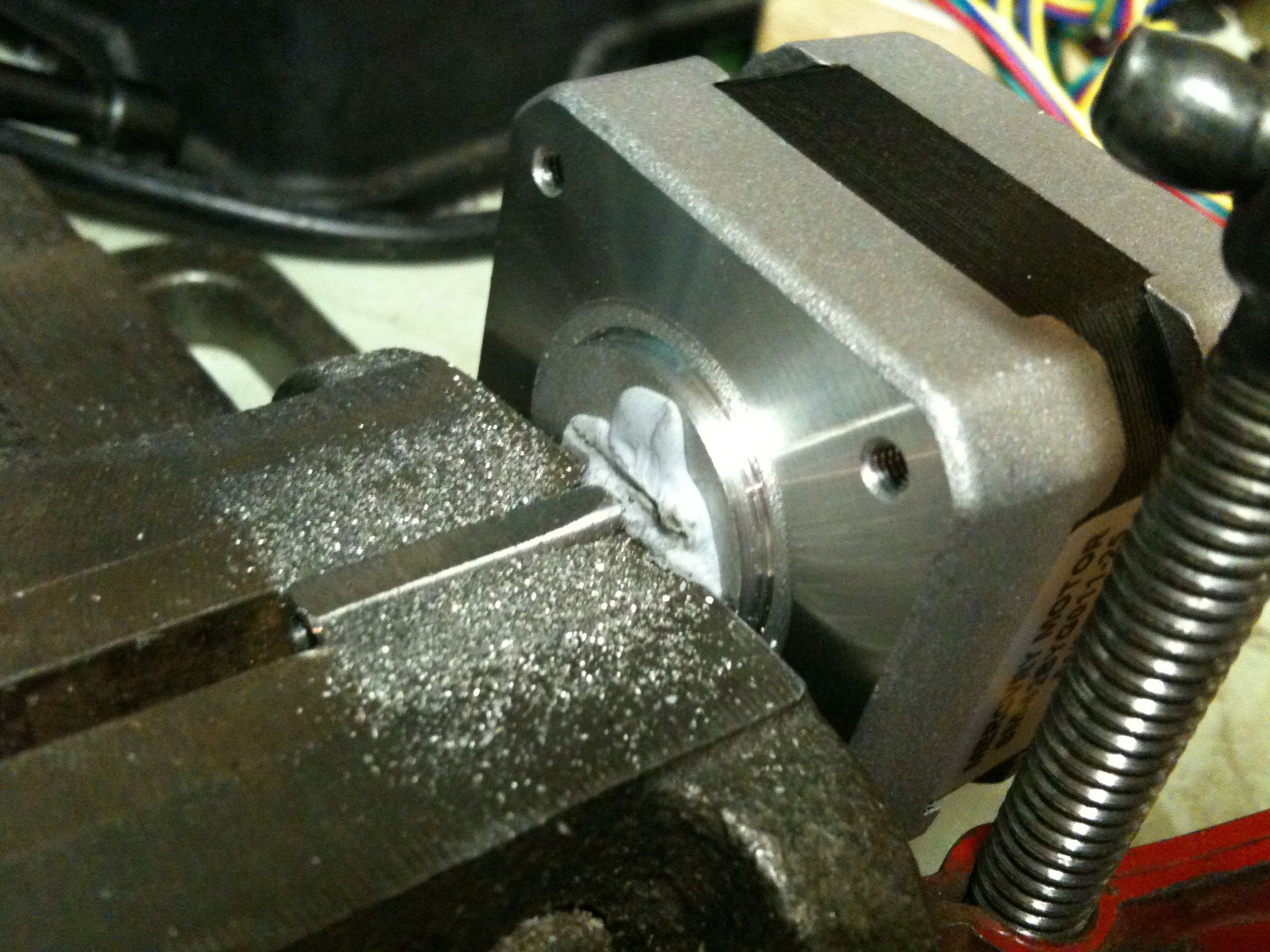
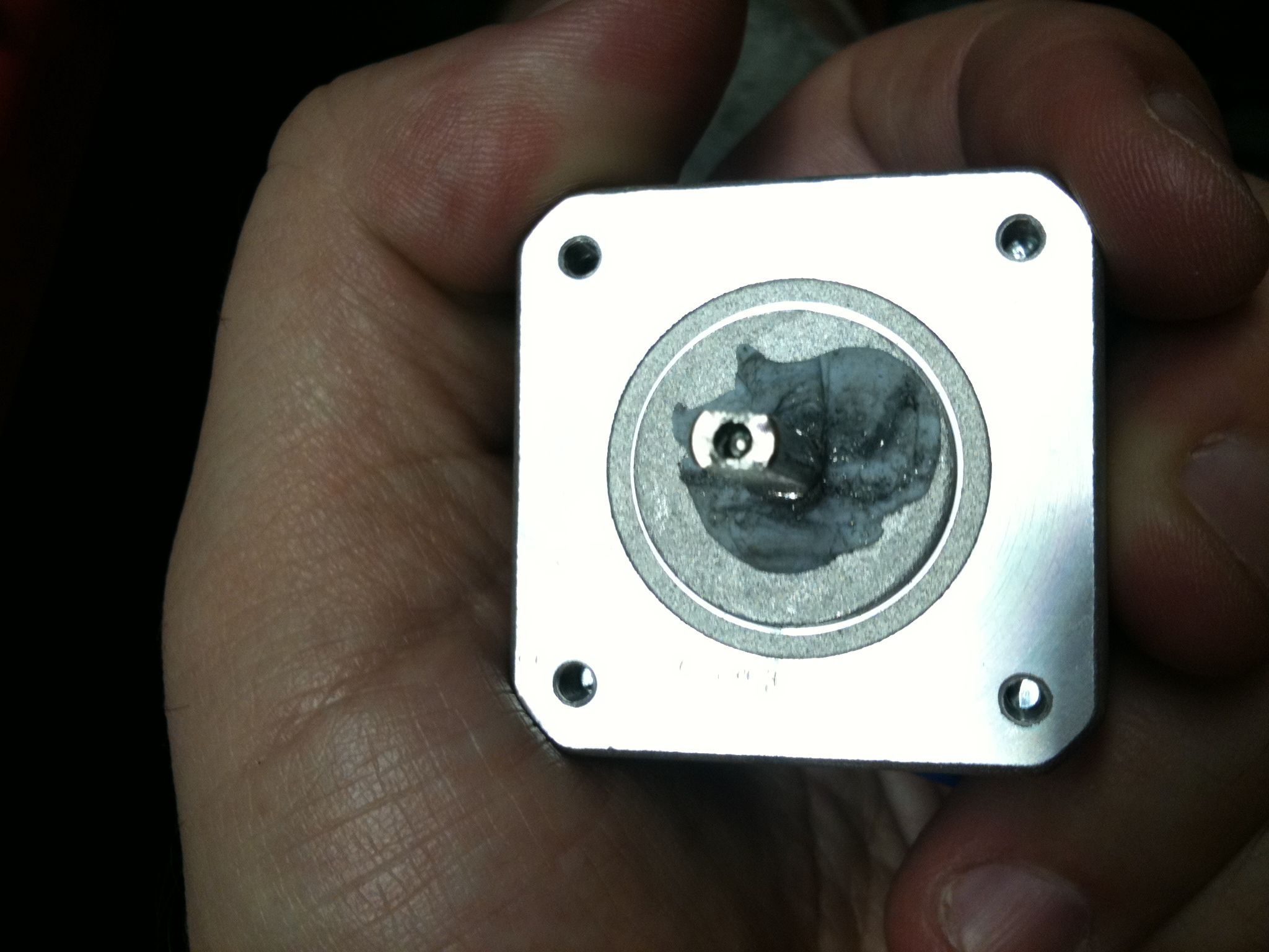
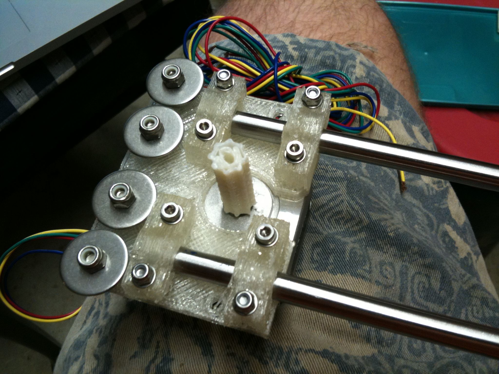
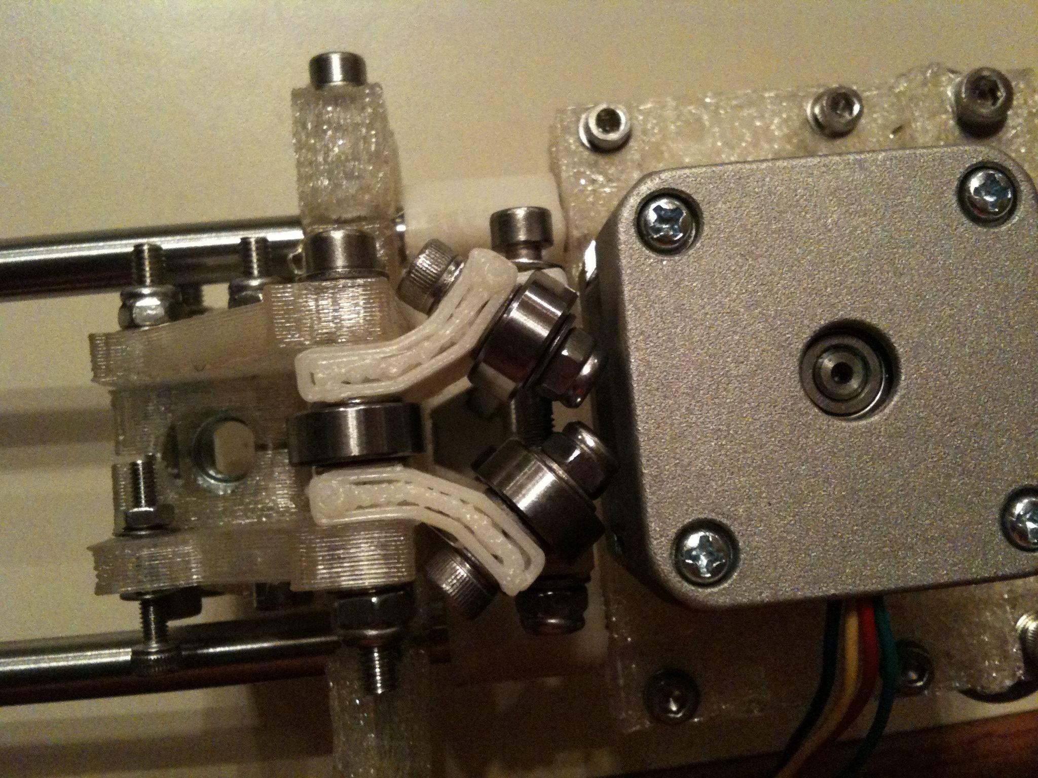
The y motor bracket assembly:
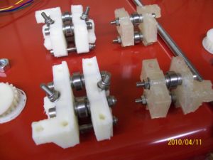
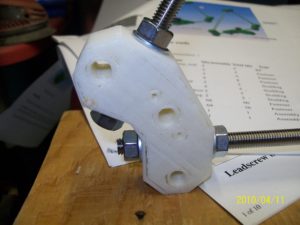
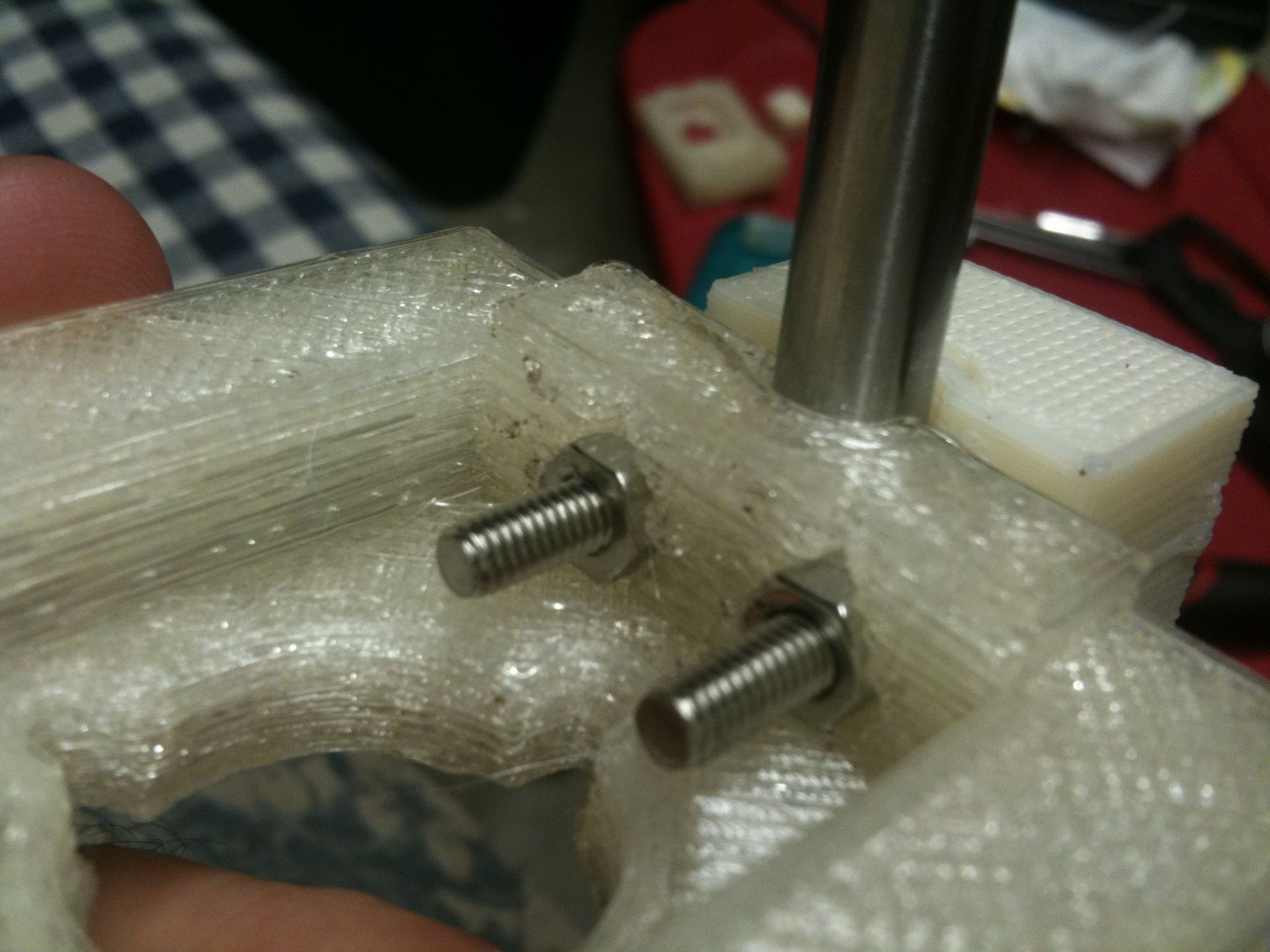
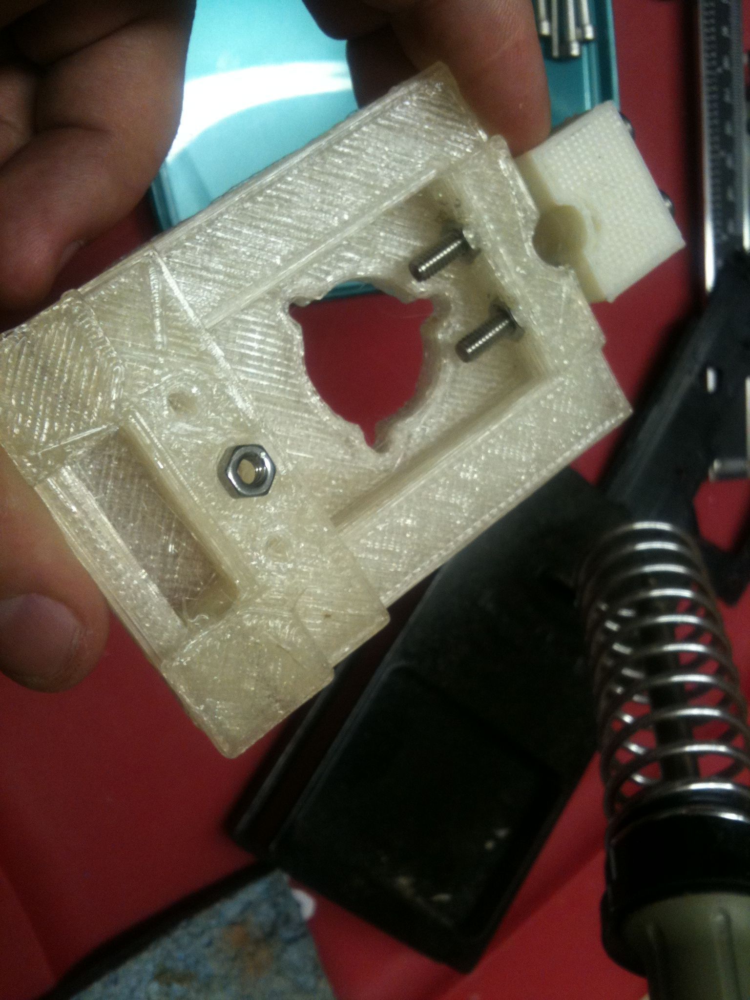
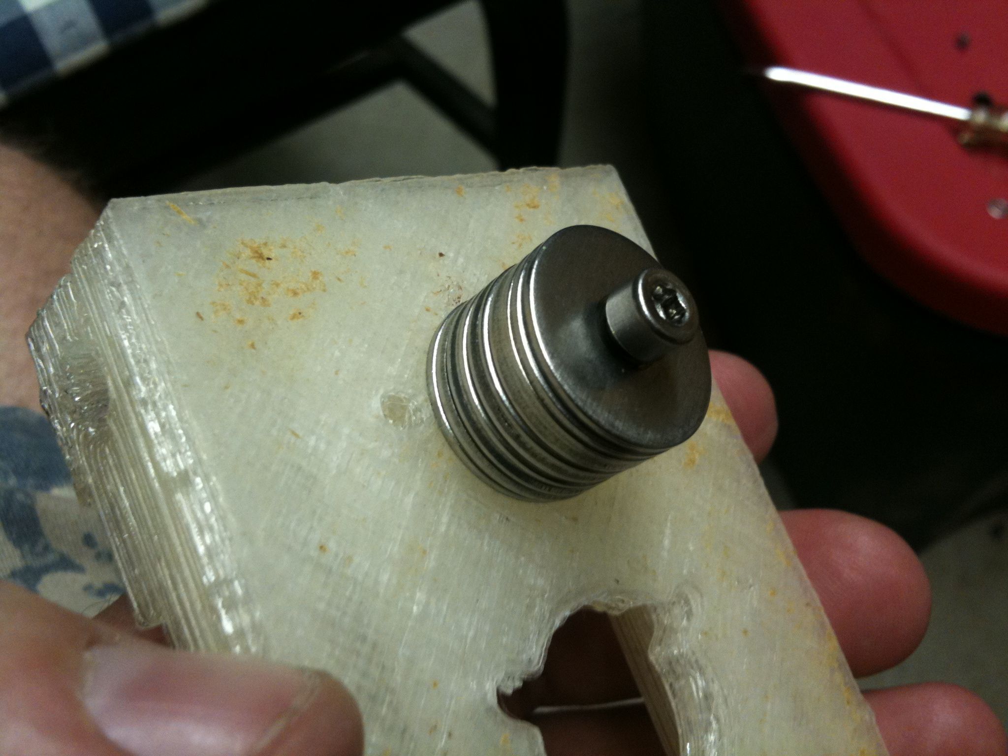
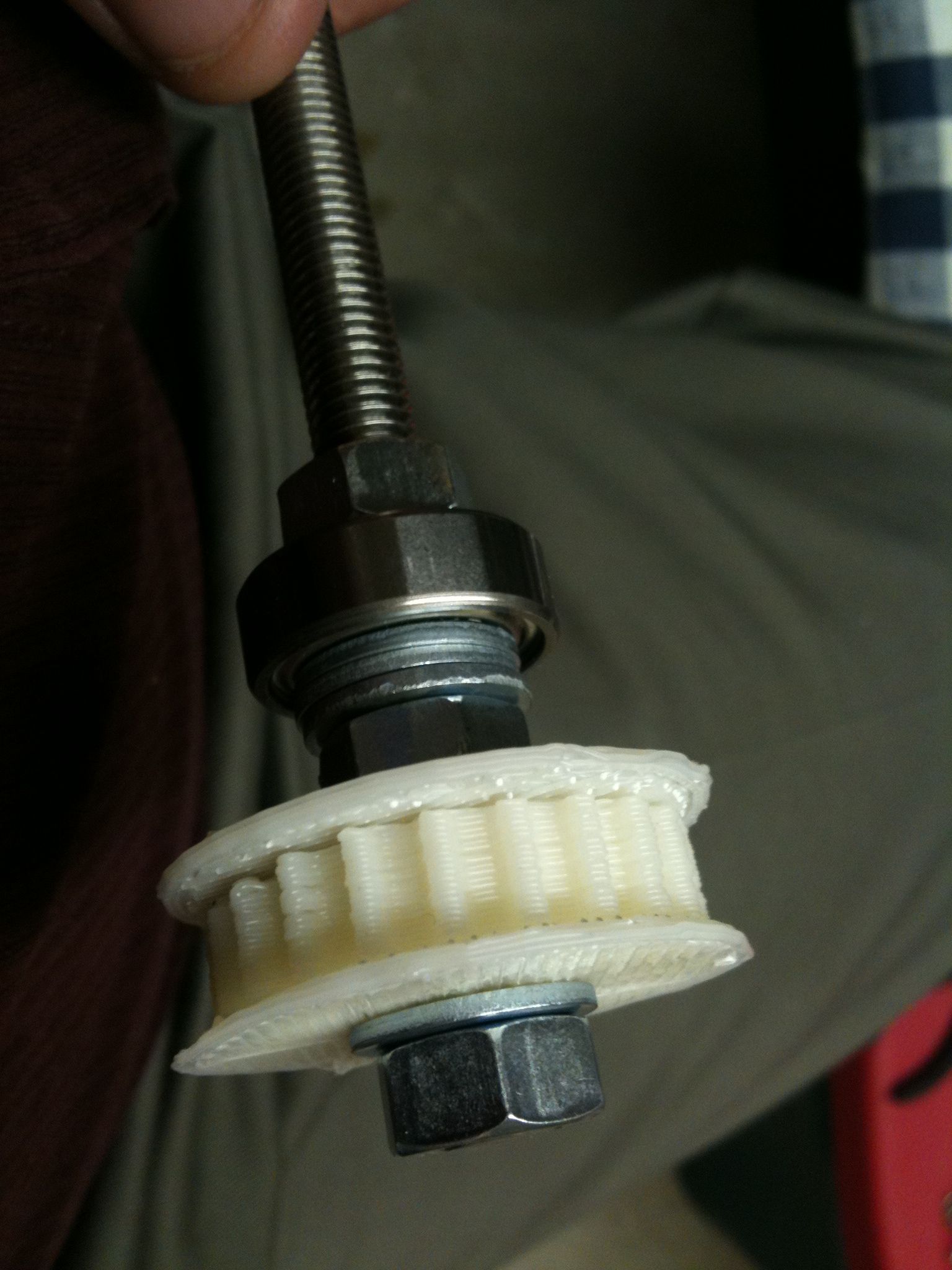
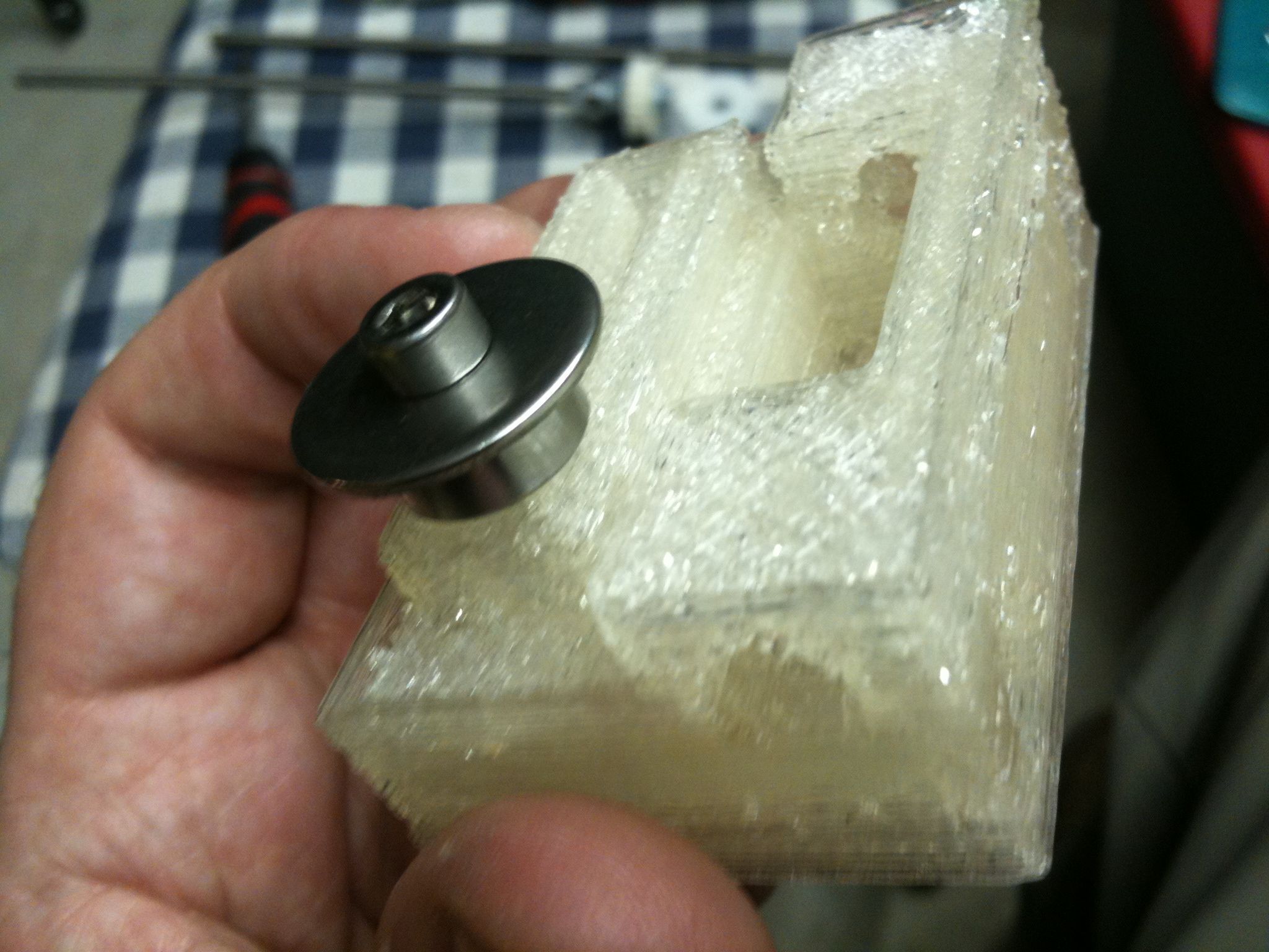
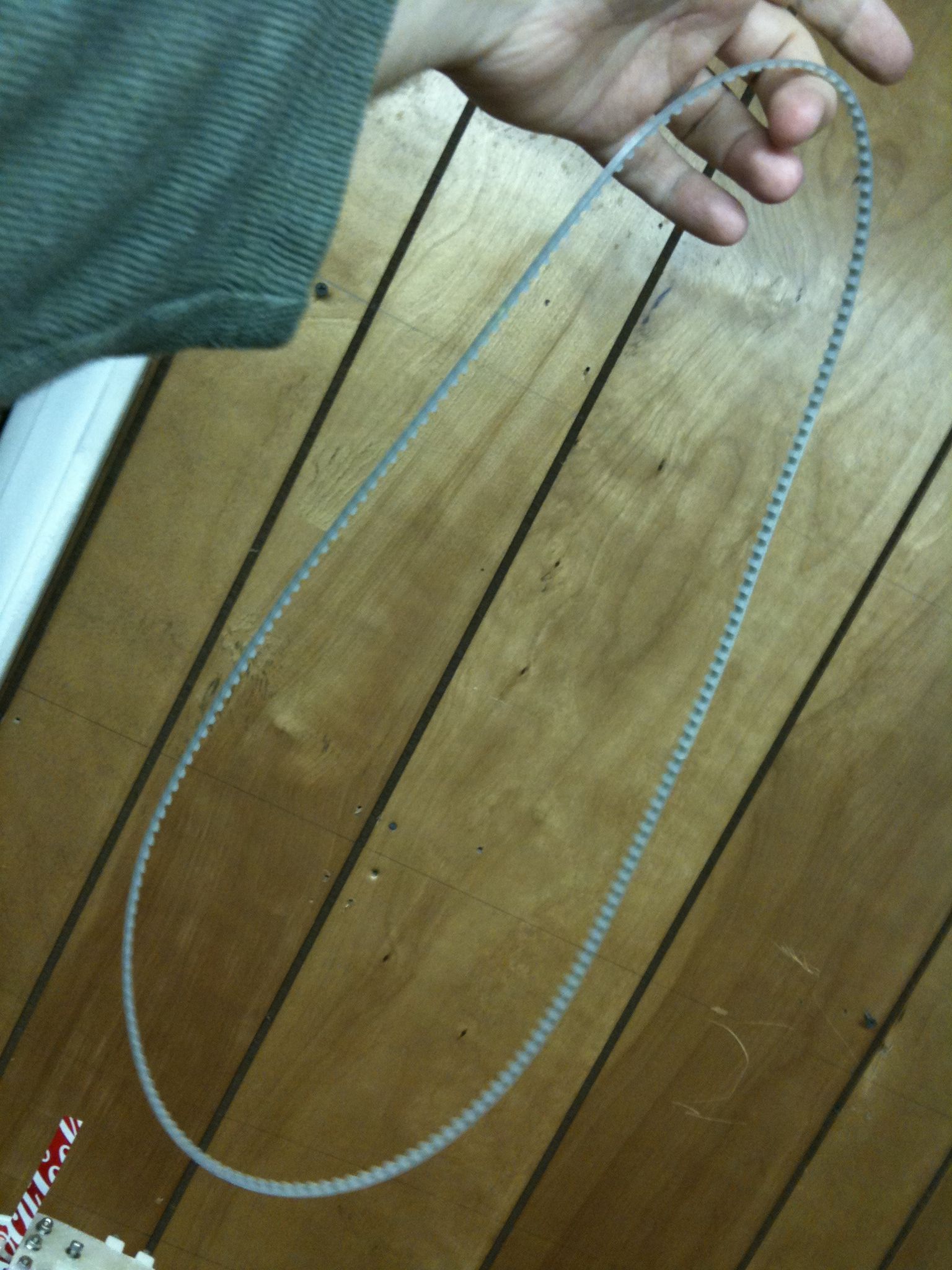
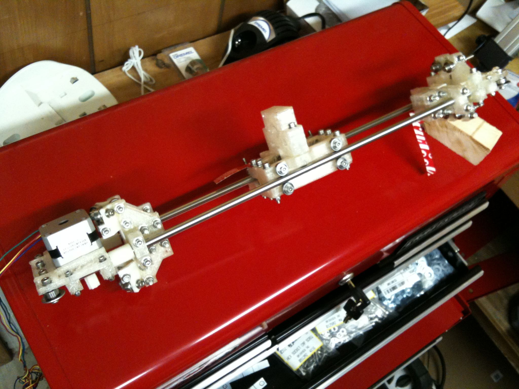
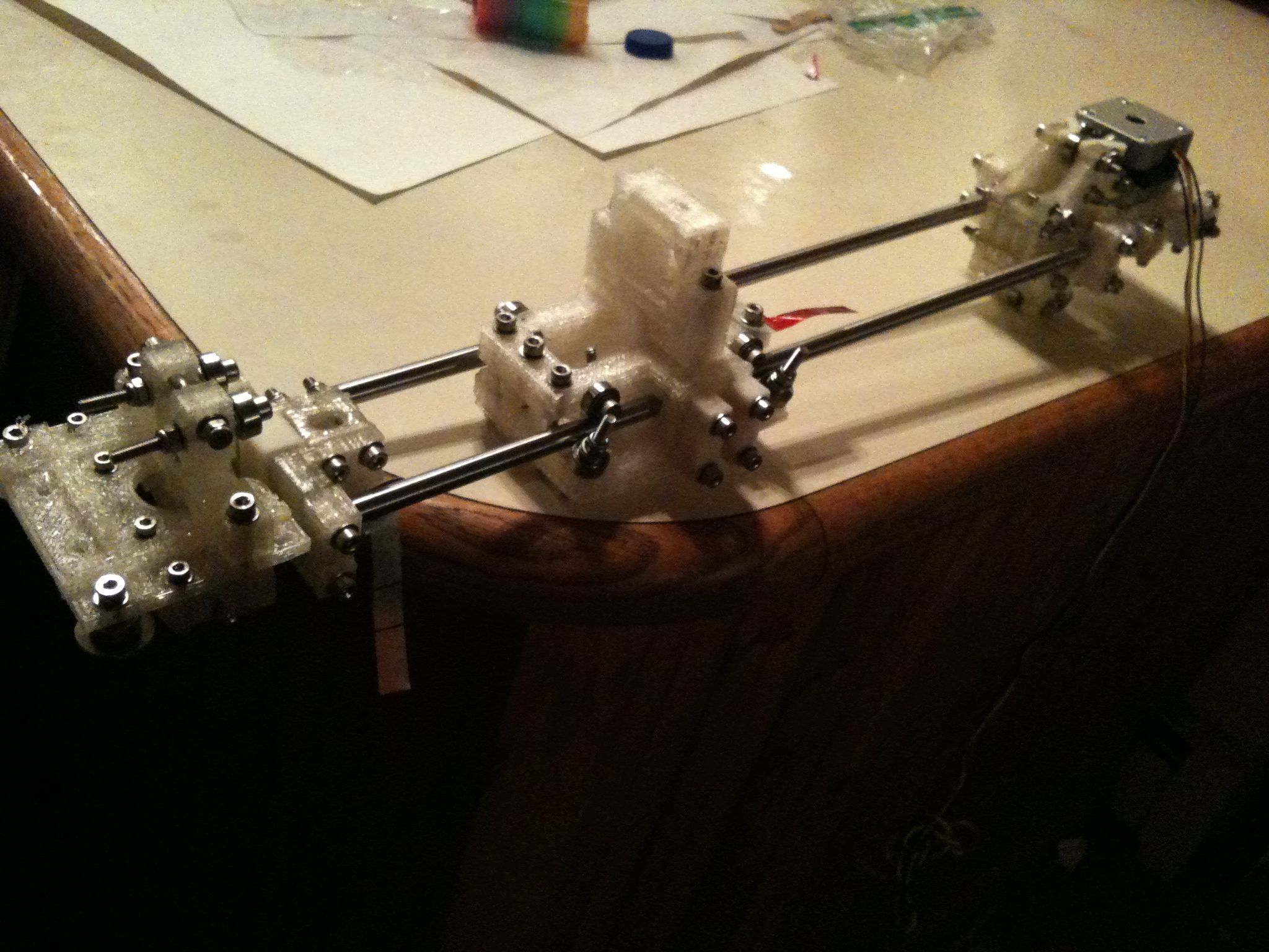
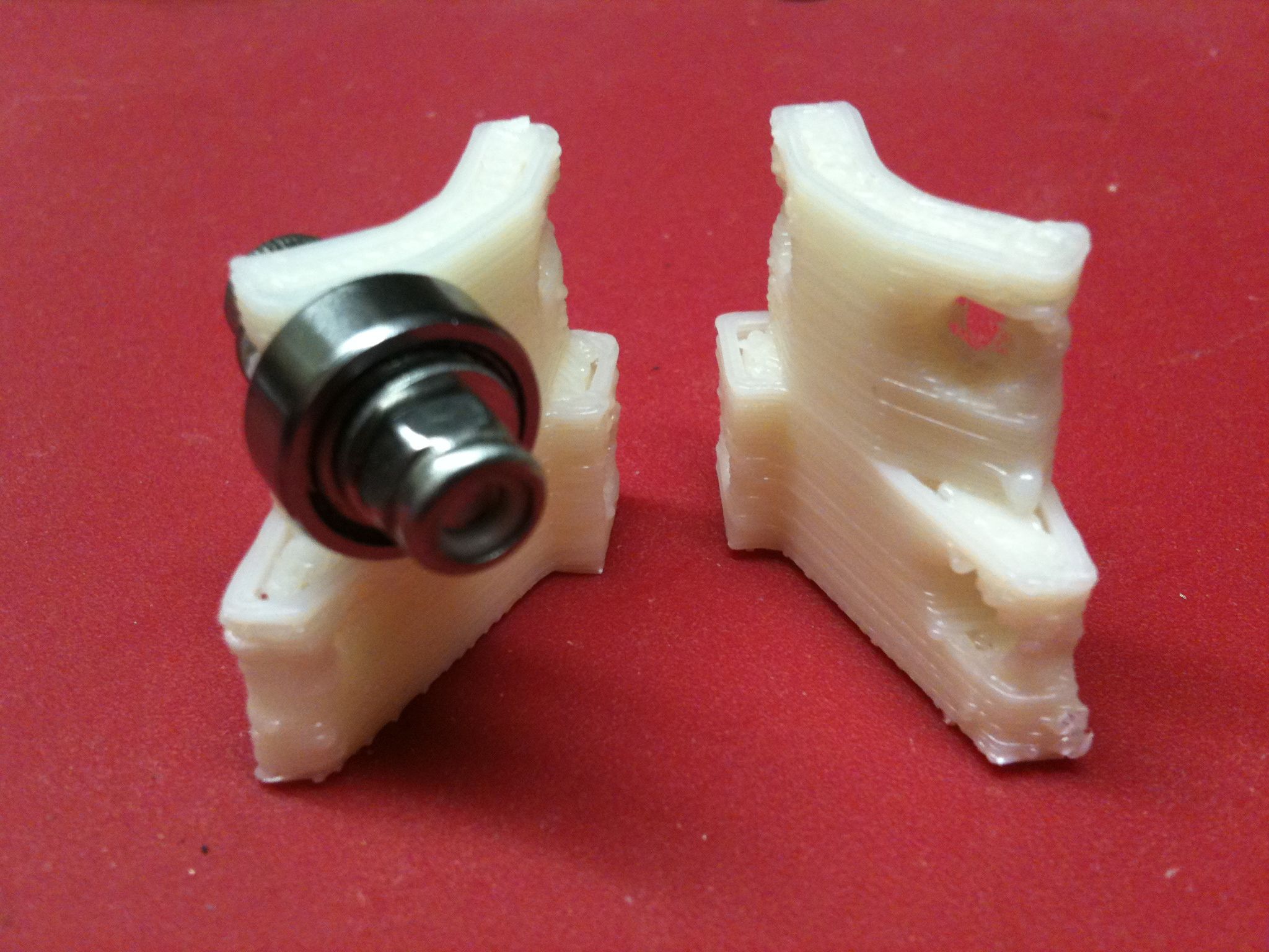
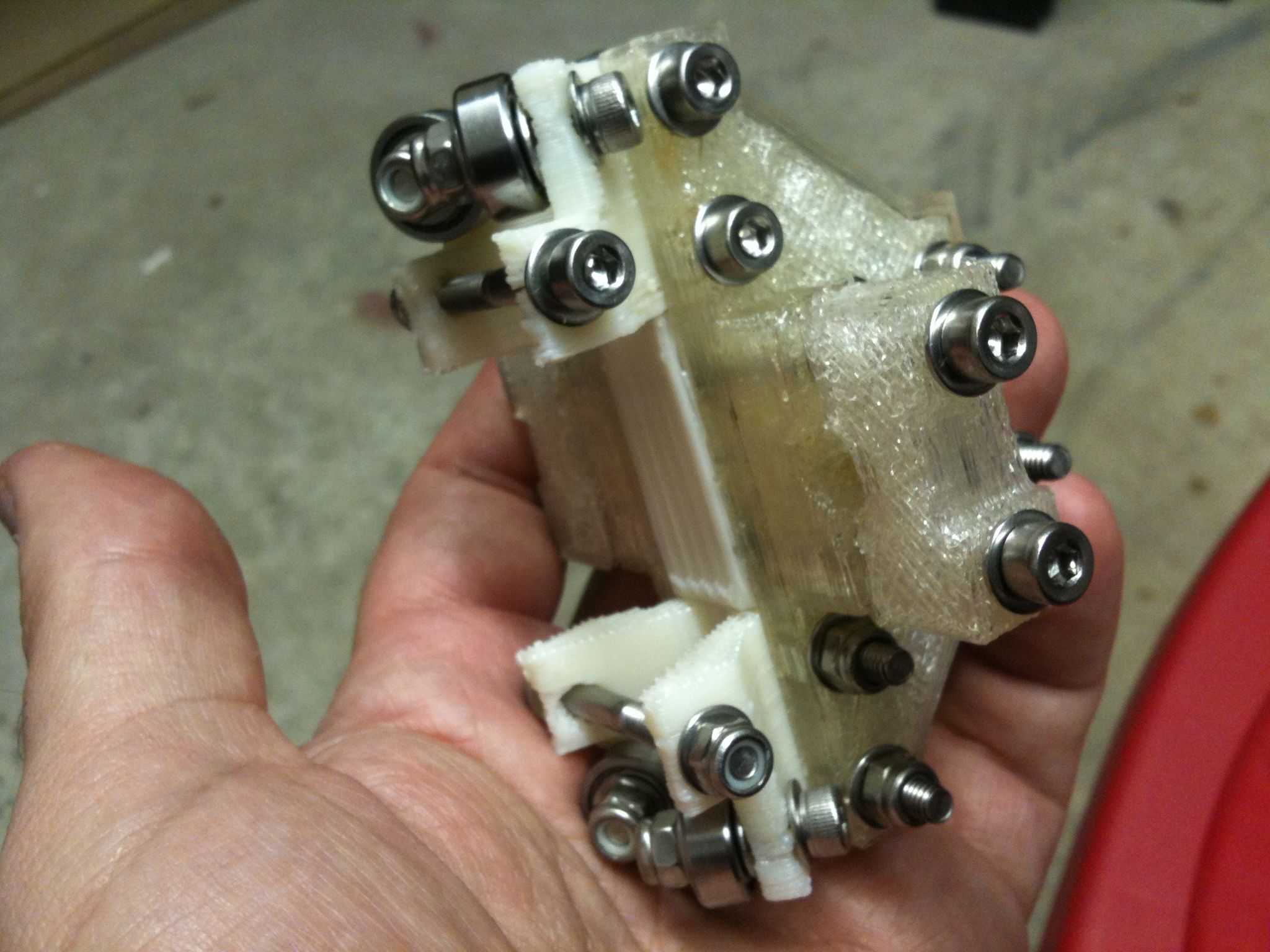
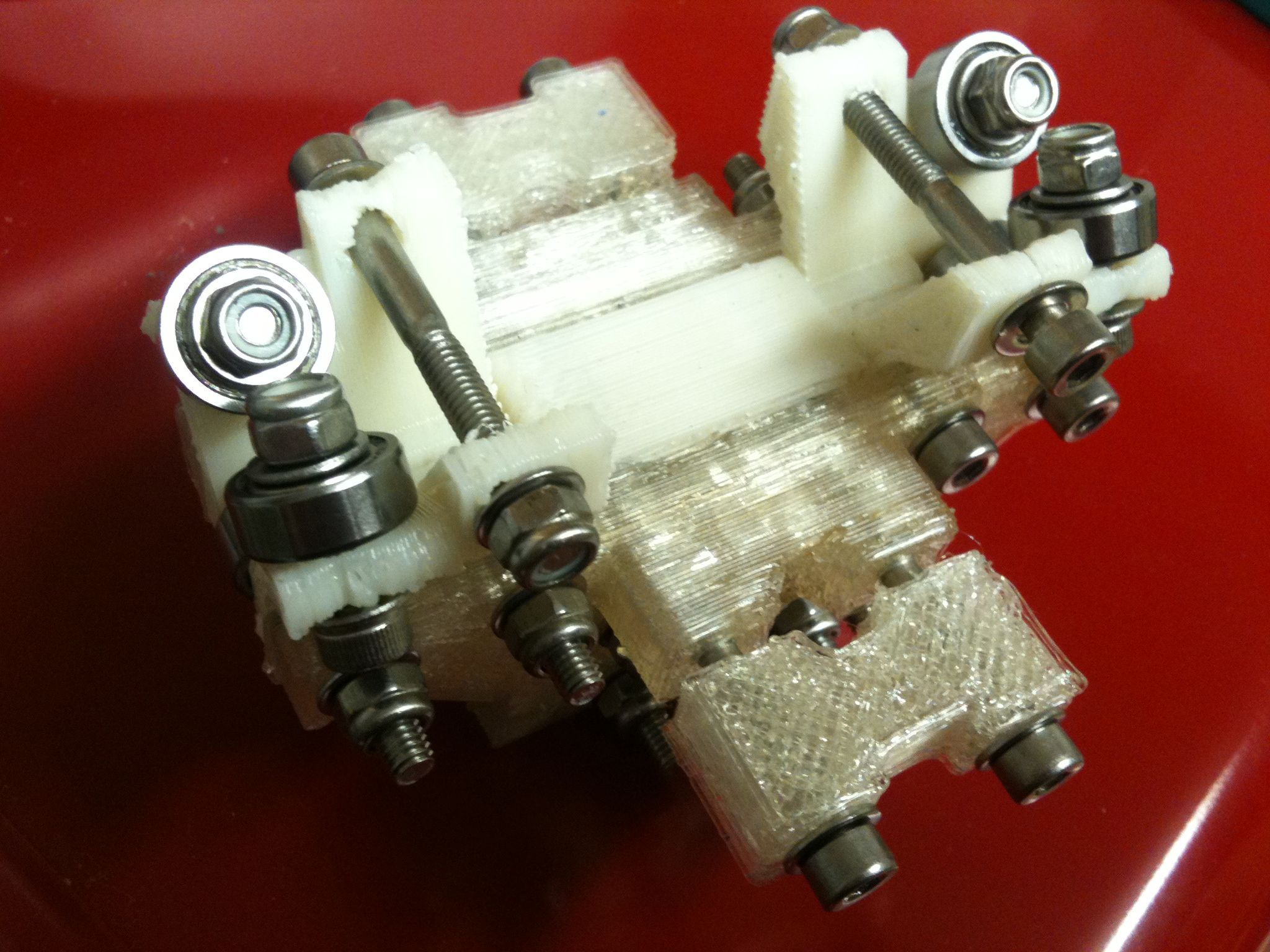
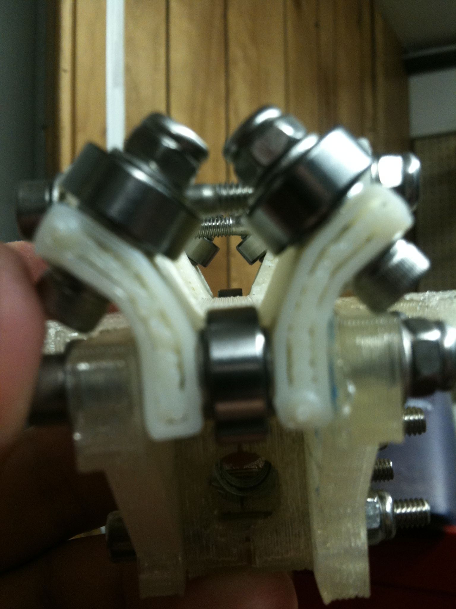
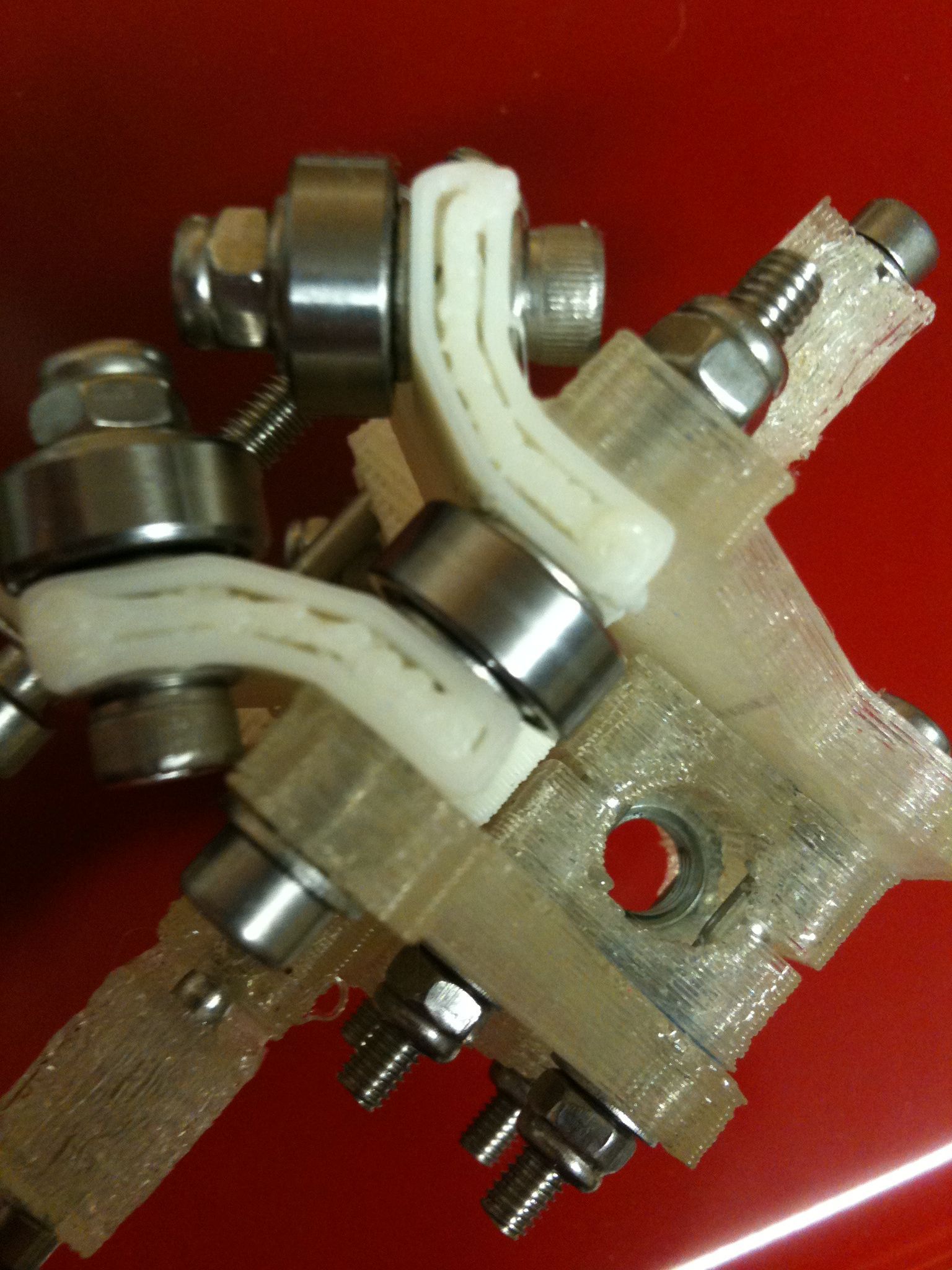
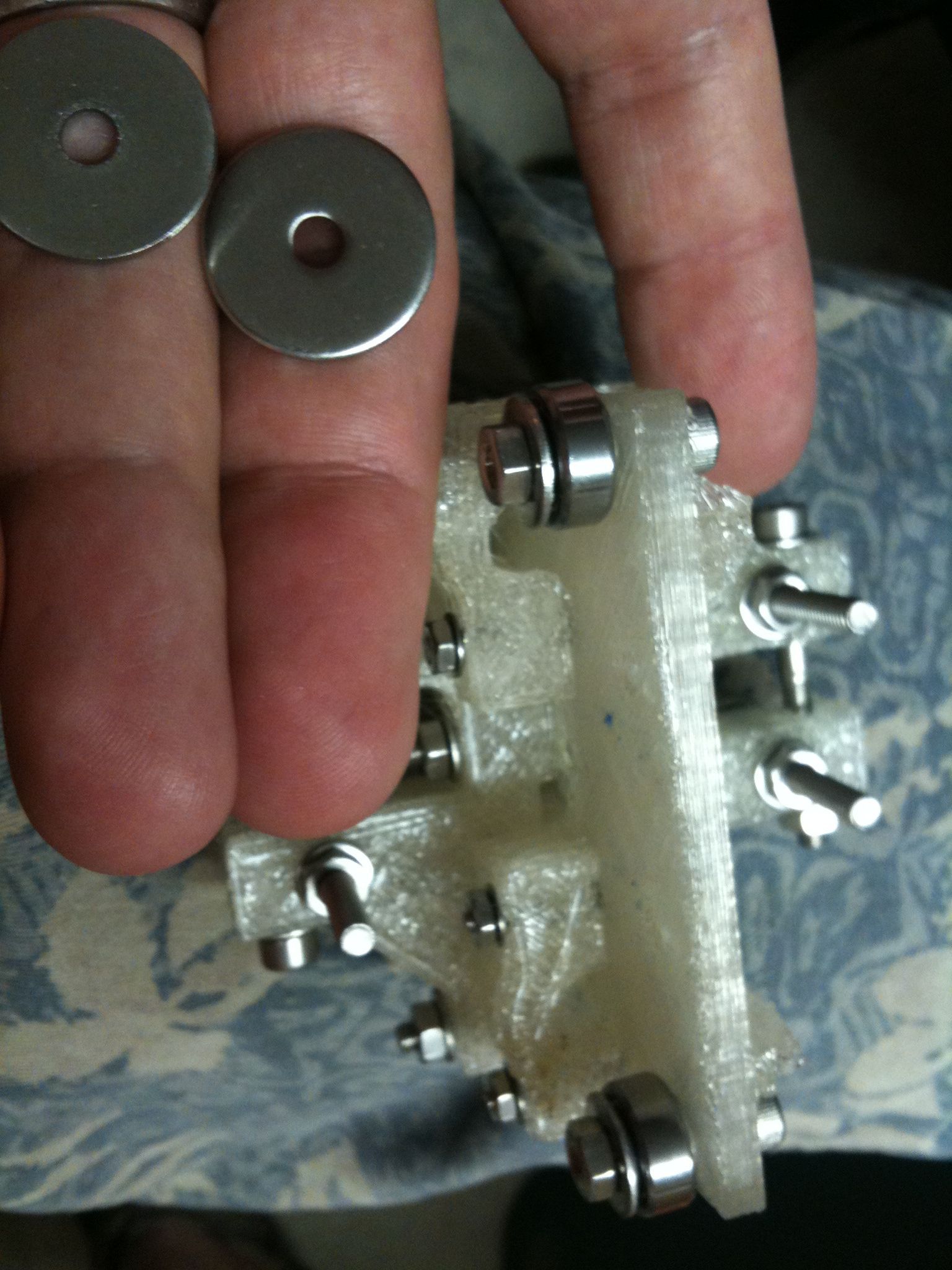
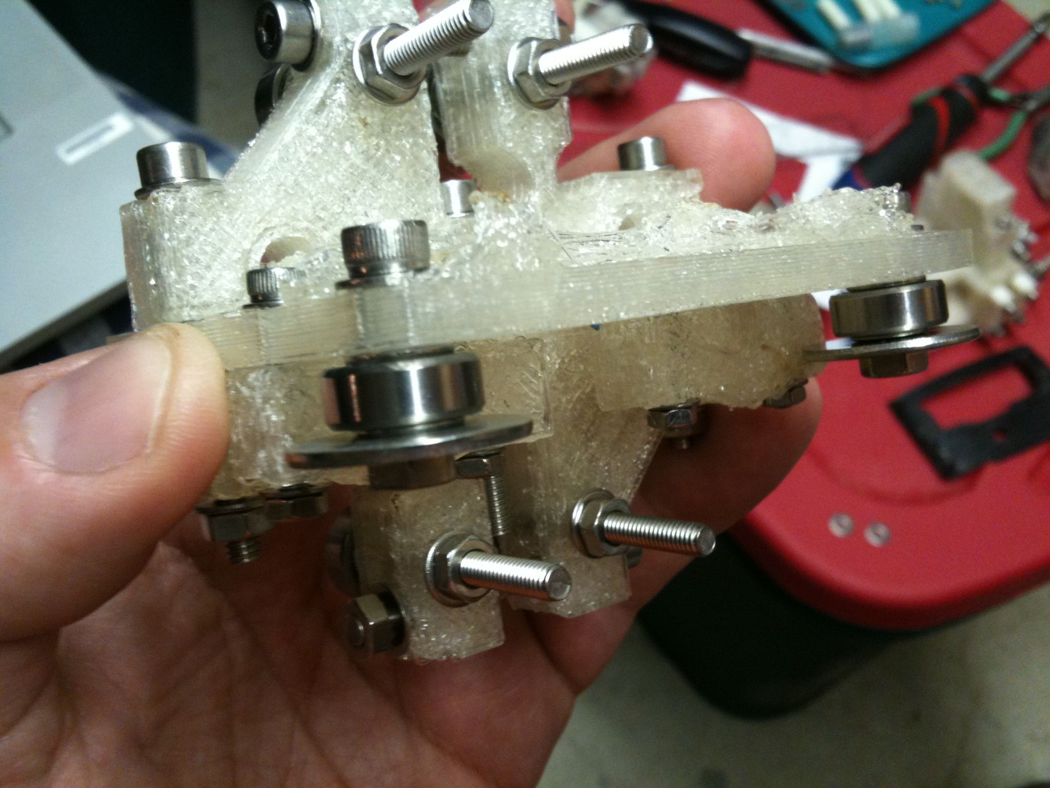
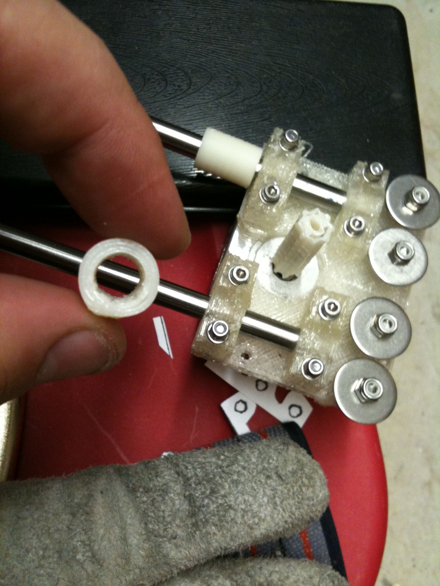
The y-bearing-360 (left) and y-bearing-180(right) assemblies:
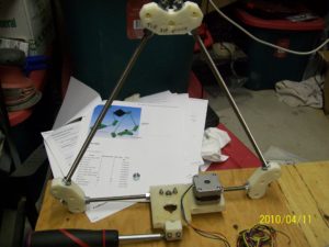
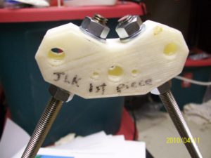
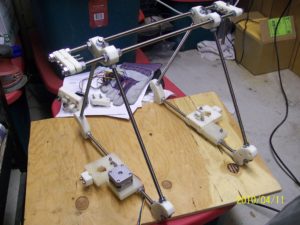
Then, I skipped part of the Y axis steps and put off affixing the Y axis components to the MDF and frog, moving on to the frame (I couldn’t help myself). Here’s the first side that I assembled, with the first piece that I’d printed for my Mendel on the top:
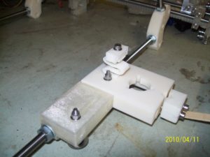
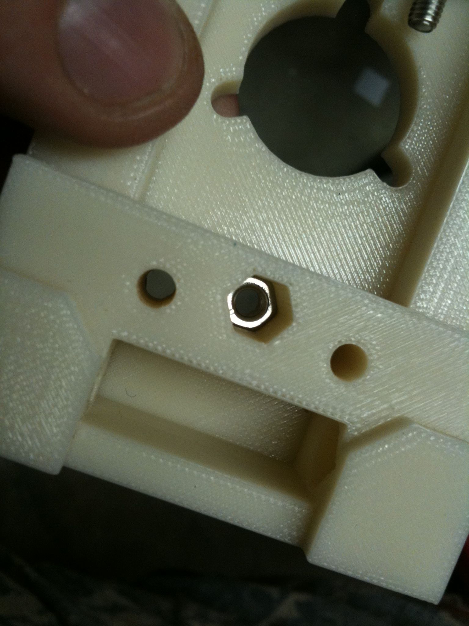
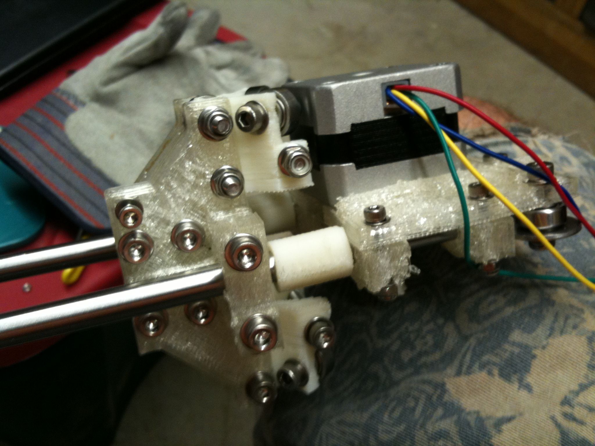
This is the Z motor bracket on the bottom, along with one of the z-leadscrew-base assemblies (this is the one that I had a stray extra bolt stuck in, from the last post):
The Mendel rests on the edges of the bottom frame vertex pieces. At some point I’ll probably put some foam padding on the bottom of the feet.
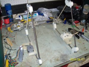
Once I built the second side (the next triangle, with another z-leadscrew-base and the z-tensioner assembly), I stood the two of them up next to each other (with the X axis behind them) to see what the tent-shape will ultimately look like:
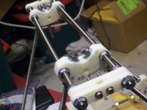
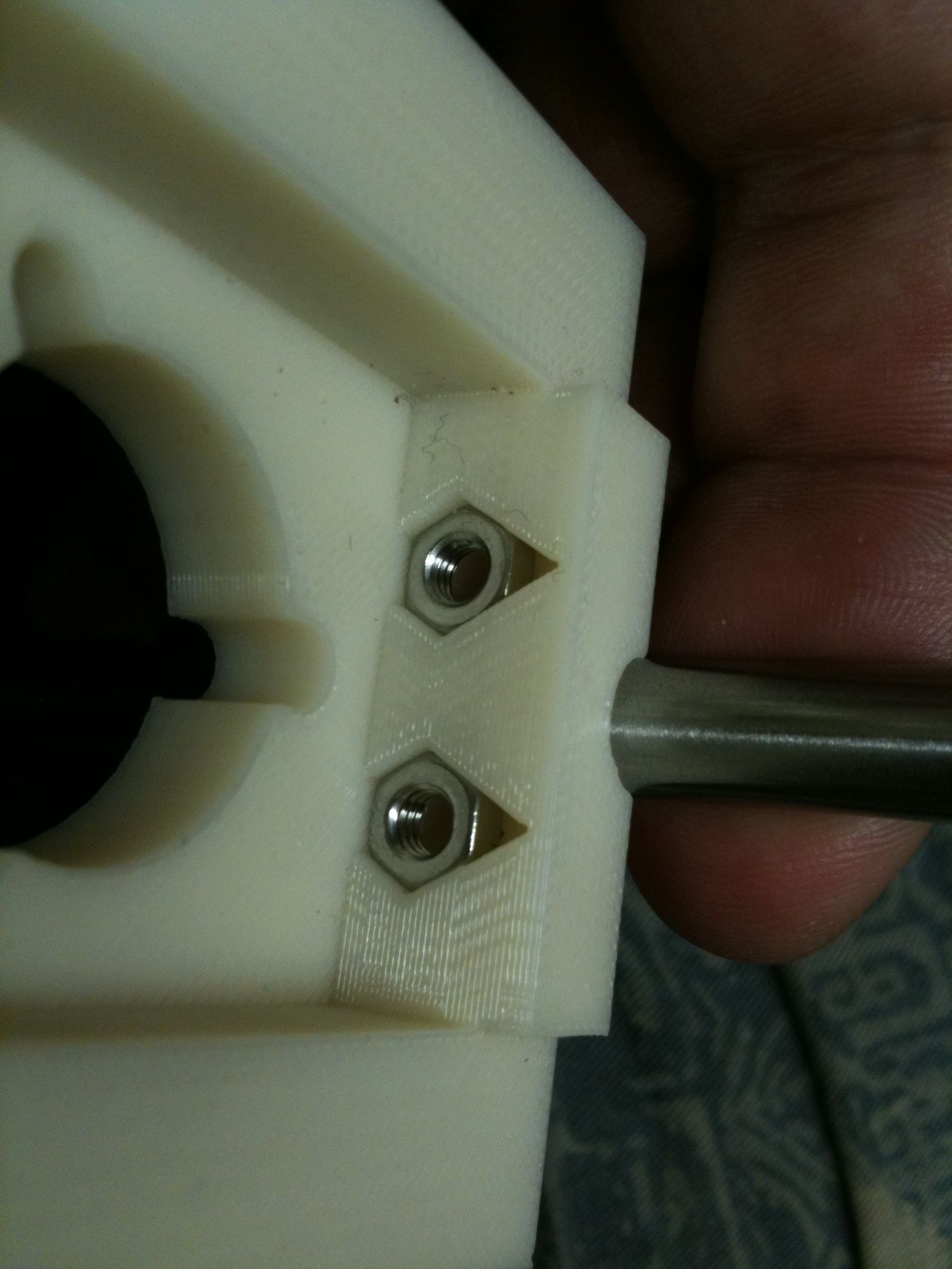
Here’s a closeup of the base of that second triangle, showing the upside-down z-tensioner piece made out of PLA, and the z-leadscrew-base that had the opto spring mounted on top of it with the long screw (described in the last post):
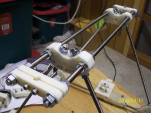
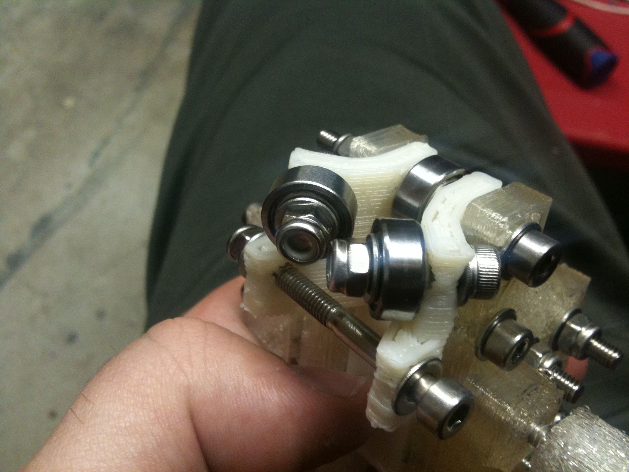
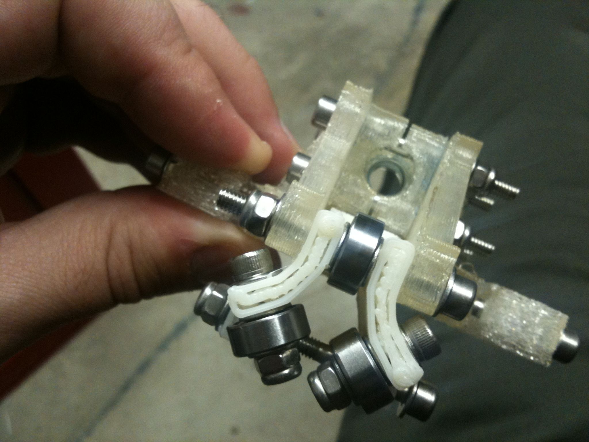
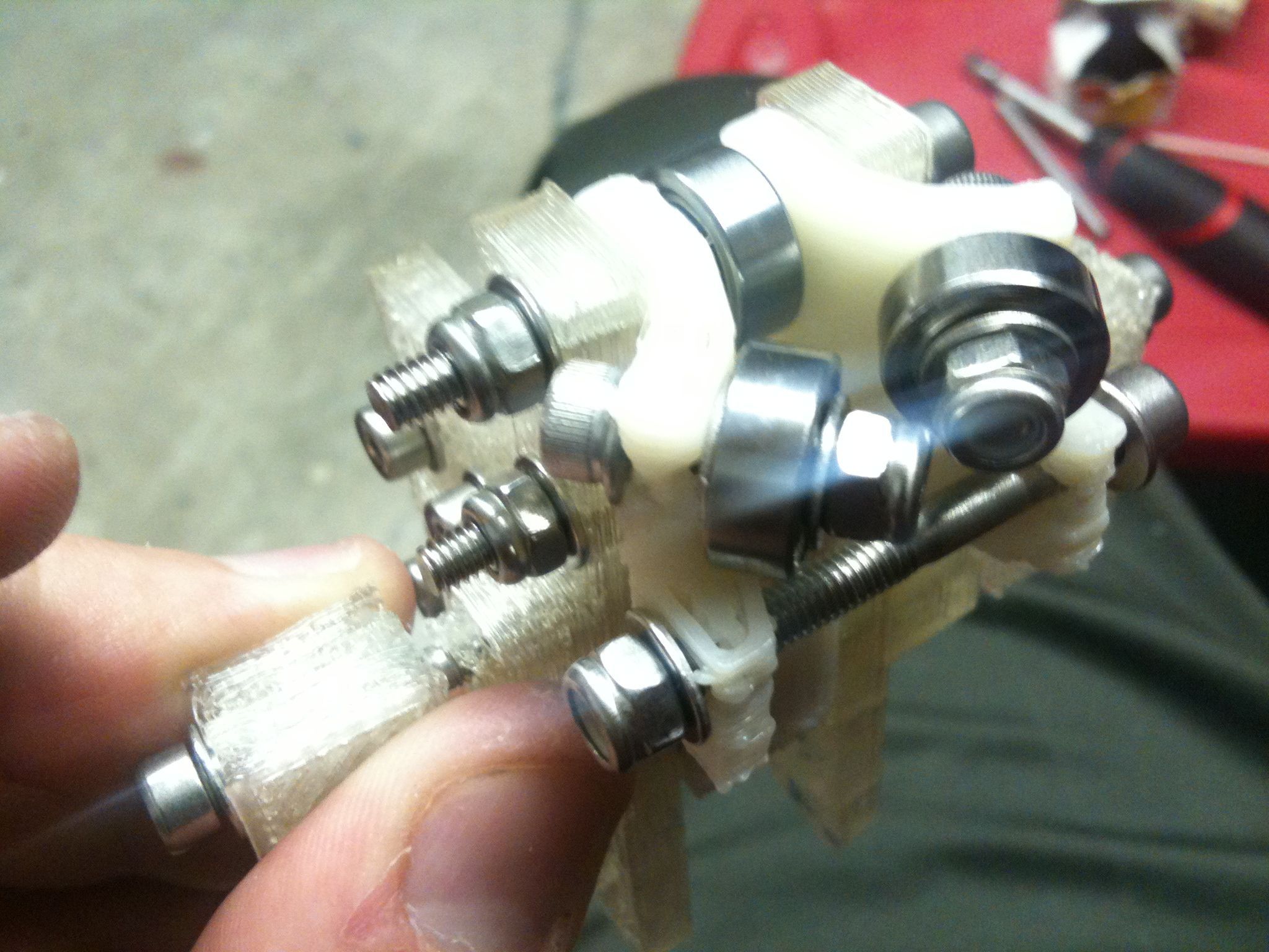
Immediately after that I proceeded to put the two sides together. This involved taking a long threaded rod, putting it in the chuck of my hand drill, slowly feeding it through the pieces on the top (ensuring the proper distances the whole way, and placing washers and nuts on as I went). It was actually kind of fun. Here is the way-cool result of all of that work:
There ya go. Wow that doesn’t look nearly as good with those tiny thumbnails. 🙁
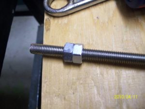
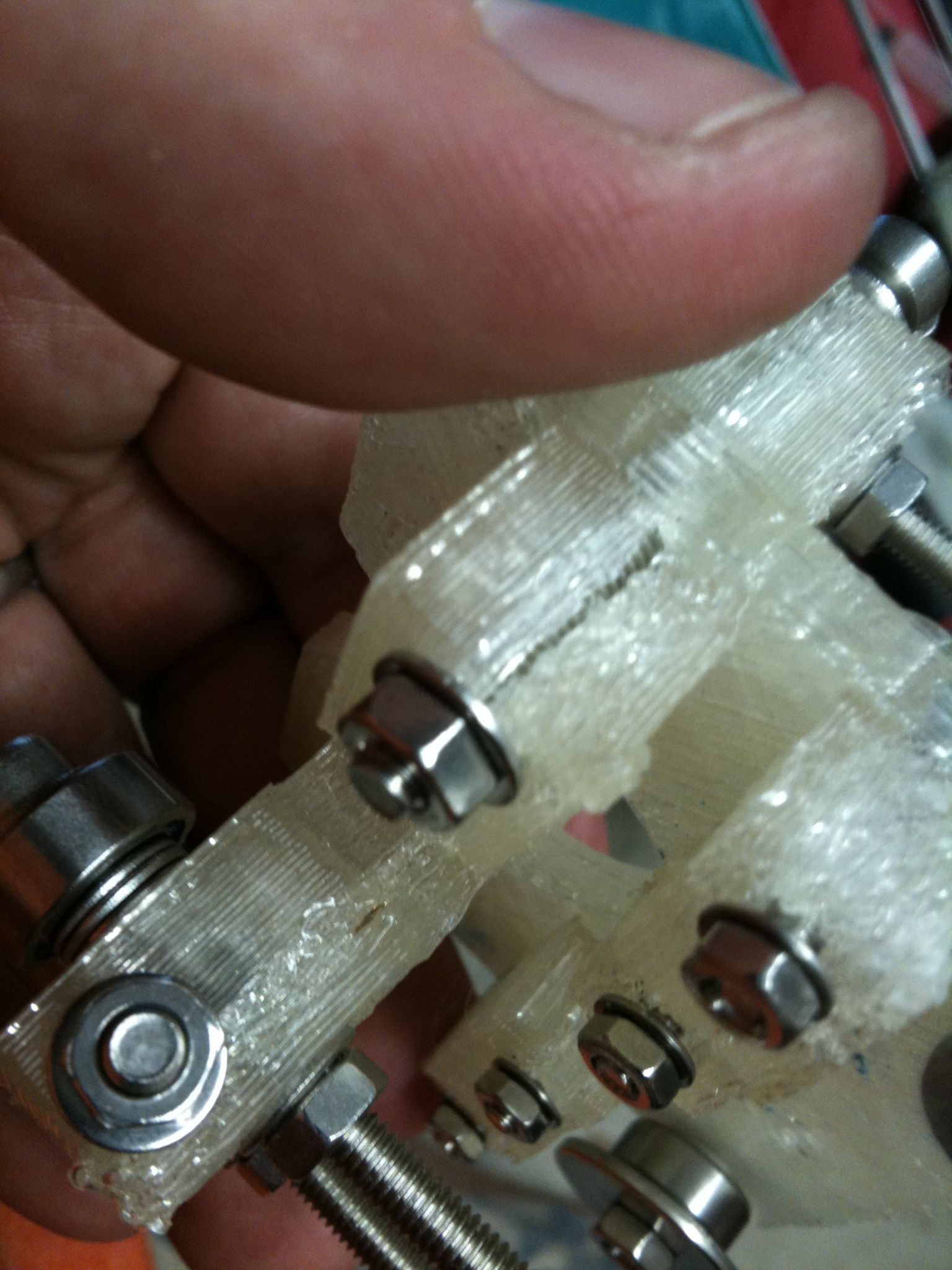
So there’s one last picture from last weekend.. While slowly drilling/driving one threaded rod through on the bottom (after the above pictures), once it made it through the z-tensioner piece (made out of PLA), the rod started to jam up and wouldn’t turn any further. Once I unscrewed it and looked at the rod, I saw the threads seem to actually have been changed/warped somehow.. Here’s the picture – the strange threads on the left are thicker than the normal threads on the right:
Yeah you can’t see that at all unless you zoom in. At first I thought maybe the metal from this rod scrapped against the metal from the crossing rod inside the z-tensioner piece, but I don’t think that’s it. Then I thought maybe the threads were caked at some very very fine level by melted PLA.. I tried screwing nuts onto the rod with two wrenches, but could only get so far before it became almost impossible to move. I also tried my tap and die set on the rod, but didn’t try for long before I gave up. I’ll have to take another look at that and see what I can do. Not crazy about being held up by that.
Hopefully more progress soon!
