Well it’s been almost two weeks since my last update, and a lot has happened. Most of it great, with a few setbacks. Lots of pictures.
Up front, the two unresolved setbacks:
Leadscrew problems
Ugh.. Motherboard flashing green briefly then just red
[Edit: I resolved the second problem.. It was a bad power supply. See first comment of this post.]
If you know of anything that can help me with either of those, please let me know.
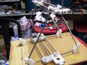
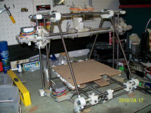
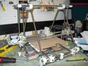
Ok, so let’s start with two weeks ago. I’d said that it was finally looking like a Mendel, but it wasn’t even close to that yet! NOW it looks like a Mendel! Here are pics I took going from last week until now.
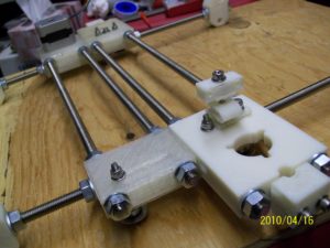
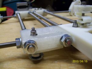
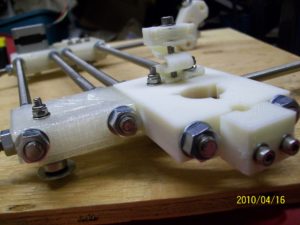
First, I screwed through rods on the bottom, connecting the leadscrew bases to each other and the z-motor bracket to the z-tensioner.
(you can see the mistake bolt on top of that leadscrew base in the last picture, which I talked about in a previous post)
Here’s the same picture taken with a flash, for what it’s worth.
Then, I screwed in the two rods that go in the front two frame vertex pieces, which go through the y idler bracket. As you can see there were additional nuts/washers that I had to have in place for holding the y axis later.
Here’s a quick picture of the bottom of the z-motor axis and a z-leadscrew-base (the entire mendel is turned 120 degrees, resting on one of its sides). You can see the geared pulley at the top on the stepper motor shaft. More on that later.
Then I screwed through the bars on the rear frame vertex pieces, including the y-motor-bracket. Same deal with the additional nuts and washers.
Next, I turned it on its side again, rested the X-axis-assembly that you’ve seen in previous posts inside the frame near the top, and screwed both leadscrews through the z-leadscrew-base assemblies. In this picture, looking at the bottom of the Mendel, on the left and right you can see the oreo-sandwiched rims and gear on the bottom of the leadscrew. The top of the leadscrew is way down in the back, screwed into the x-axis.
Here began one set of problems I ran into. First, when I’d screwed the left leadscrew into the x-axis (into the vert-bearing-360 piece), the bottom of the leadscrew “wanted” to be off-center.. I had to push the screw to the side to get the bearing to fit into the leadscrew base (you can’t see the bearings in the above picture – they’re behind the rims/gears). This caused the left leadscrew to not turn easily.. The one on the right turns fine, but not the left one. This is a major problem. I tried adjusting the z-bar-top-clamp pieces on the left to one side or the other, with limited success. I even purchased a new smooth rod in case somehow I bent the previous one via cutting, but experimentation with that shows that the original rod was probably fine The closest I have to something that works now is if I have the z-bar go all the way down then not actually get clamped in at the bottom.
But anyway, at the time I didn’t realize that was as big a problem as it was, so I pressed on (constructing things that I may have to disassemble later, especially if I have to take apart the vert-bearing-360 piece of the x-axis).
So the next problem with the leadscrews were that they were now the bottom-most piece on the Mendel, which is wrong.
It’s supposed to rest on the frame vertex pieces, yet my leadscrews were lower than that (which apparently others have run into, leading to
this alternate frame vertex piece with feet.
Frankly I’m stunned that this works for anyone, as I followed the instructions to the letter. Perhaps the thickness of M8 nuts varies? Or maybe it’s implied that I should remove some of the washers in the leadscrew assembly? Whatever – for now, I have to prop the four feet up on 4 small scraps of MDF.
So with the x-axis assembled, I rotated it upright to take a picture or two. Note that the x-axis stayed up because it was incredibly difficult to turn the left leadscrew, so I couldn’t even lower it at first.
If you’ve got a keen eye, you might have noticed that in two of the last four pictures you could see that I also installed the z-axis belt on the bottom, connecting the two leadscrews. That’s more visible here:
and you can see it clearly here:
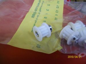
I’m gonna jump ahead in time a bit now. What didn’t help there, nor did it help on any of the axes, was that all of my pulleys were wobbly. I’d had a hell of a time getting them on the shafts in the first place, and they were all off-center. I posted a question about that here, and someone suggested buying actual purchased pulleys from McMaster, which would fit the belt but would have 10 teeth instead of 8, providing less torque but more speed. At $7 each I figured why not, and bought some – I can always print more pulleys once I have this working. (I also read confirmation from others that the firmware could be adjusted to accomodate the larger pulley size). The purchased pulleys (McMaster part# 57105K11) look like this:
They come with their own set screws. So once I removed the y-motor, removed my printed pulley, and tried putting on the McMaster pulley, I suddenly realized why I’d had such a tough time putting the printed pulleys on my filed down stepper motor shafts.. They were the wrong diameter!! Originally I’d purchased 4 MakerBot Kysan stepper motors, then incorrectly thinking they didn’t have enough torque, I bought 4 more on a whim along with another purchase I was making at sparkfun.com. When I finally got around to deciding which motors to use and calculating their actual torque, they were just about the same, with the sparkfun motors having sliiiightly more torque, so I used them. They seemed to be NEMA 17 size, screwed in fine, etc. But apparently the shaft was slightly larger, because when I tried putting the McMaster pulley on the filed down stepper shaft it wouldn’t fit, but it did fit perfectly on the Kysan motor. Doh.
Ok, jumping back to where I was..
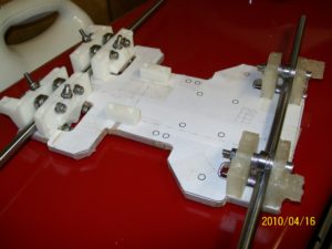
So next up was the Y axis. I took the y-axis pieces, threaded two y-axis bars through them for show, and placed them where they’re supposed to go on the “frog” piece of MDF. Now that I see how they’re supposed to fit, I think the frog layout was pretty damned cool.. The pieces fit in snugly even before I screwed in anything.. Excellent design!
That’s the piece that hangs below the y-axis bars and slides back and forth.. Above that is mounted the actual bed that we print on. In the above picture you can also see two belt clamp pieces that will hold down the y-belt, so the y motor can pull the whole assembly forwards and backwards.
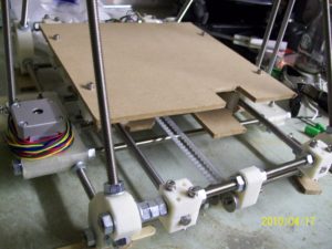
The next pictures I took were after screwing down those pieces, tearing off all of the guide paper, screwing on the extra little plate for excess plastic, mounting the y-axis bars in the mendel (with this assembly in place), putting on the bed springs, and screwing on the bed:
Here you can see the bed springs on both sides:
and the z-belt y-belt connected to the frog:
Here’s a picture showing how the frog just barely clears the rods below it.
I tried recording video showing how sporadic the movement along the Y and X axes were because of wobbly pulleys (remember, this is before I received any McMaster pulleys). I was using Laurie’s camera and wasn’t even sure that it was recording audio, so sorry about the poor sound quality and length. Around 0:12-0:16, in the back on the y-motor, you can see what I’m talking about when I use the term “wobbly pulley”.
Ok.. So later I realized that by pushing the left leadscrew to the right a bit on top, I was able to at least manually turn the leadscrew, which while not a real solution at least let me lower the x axis for a nice picture:
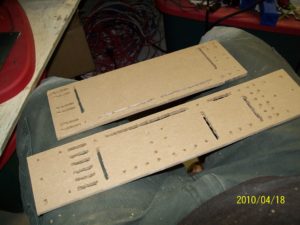
Next up was the remaining MDF pieces. They had a ton of holes and ovals to be cut out of them. Standing at my drill press for a while, I drilled all of the holes, including multiple holes where ovals were supposed to go, then used a jigsaw to cut out the oval pieces. It’s not exactly pretty, but it’ll work for mounting circuit boards, and I didn’t have to go ask anyone for permission to use a laser cutter.
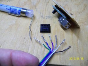
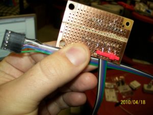
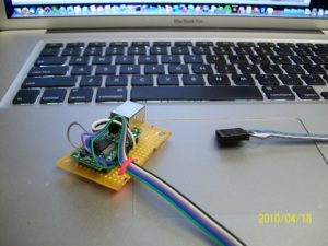
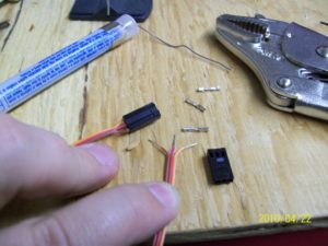
Next up, circuit boards. First, I soldered the UM232R USB-to-serial UART development module onto a piece of stripboard, cut a length of 6-wire ribbon cable, soldered that to the board, and solder/crimped the other end of the cable into a header with insert-able pin receptacles. (I later redid some of the header connections, as I got better at soldering/crimping these by hand with a vice grip tool).
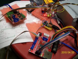
Using that board, I was able to load the RepRap Mendel FiveD firmware onto the motherboard and extruder controller board. After crimping two IDC connectors onto a 10-way ribbon cable, I was able to connect the motherboard to a stepper driver board, connect that to a stepper motor, and make the motor turn with the RepRap host software. Note the green lights on all of the boards in the picture, and sorry that the youtube clip is 100% blurry.
So with that working, I proceeded to start on the modifications that I need to make to these pre-assembled boards to make them compatible with the Mendel RepRap (they’re currently built for the MakerBot, and there are a bunch of modifications you need to make for Mendel).
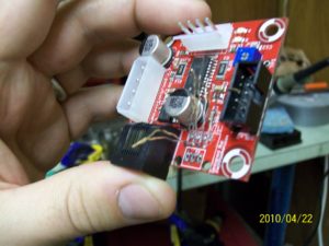
First, I removed one of the cat5 connectors from one of the stepper controller boards (which wasn’t for ethernet – it was just a wiring choice), and instead replaced it with a 3-pin header. I found that after pulling the wires to the side, it was easier to remove the black plastic first, then desolder the pins and remove them, but your mileage may vary.
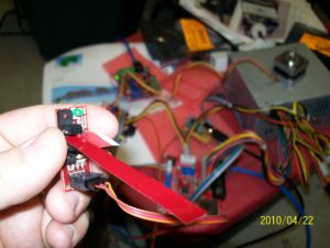
I made a 3-wire ribbon cable to connect an opto-endstop board to this header:
and after soldering another 3-pin header onto the opto-endstop board, I was able to connect the opto-endstop to the board, and verified that when blocked by a piece of Coke can (my opto endflags), the motor wouldn’t turn in the “down” direction, but when clear, it would. Woohoo!
(the flash kind of hides it, but that green LED on the opto-endstop board is lit).
Everything’s great, right? Well, no. I’d tried the same test with a kysan motor in the y-motor-bracket with a mcmaster pulley around it (after removing the bed so I could adjust the belt clamps to fit the motor), and was able to successfully move the bed along the Y axis both forward and backward. I wanted to film this but my iPhone has been full for around a month, which is why these and last week’s pictures were taken with my wife’s camera. So I went upstairs and finally carried out the last steps in getting all 5100+ pictures off of my iPhone (a boring torturous story not worth going into here). The good news is I successfully cleared off my iPhone:
The bad news is that when I went back downstairs, nothing worked anymore. [Edit: Again, happily I figured out this problem. It was a bad power supply. See the first comment of this post for more details.]Originally, after loading the FiveD firmware, a red light would flash on the motherboard when the power supply was on but the motherboard power switch was off. Upon turning on the motherboard switch, the board would light up green instead (as would other connected boards). Sadly, now when I turn on power, each connected board flashes green for like a hundreth of a second, then goes back to red. (I’ve tried having nothing connected to the motherboard, and it still fails).
I’ve wracked my brain trying to remember anything that might have gone wrong. The closest that I can imagine is that there was one point where I clicked the HOME button and it made the y-axis move forward very fast (but it was moving in the wrong direction), and it rammed into the other side before I powered it off. This kind of thing had happened with the MakerBot all the time, so I wasn’t worried that it had caused any problem. What I don’t clearly remember now (because I’ve also been very sick over the past few days) is whether I got it working after that or not. I do remember switching the stepper motor plug around (which I remembered being suggested by the MakerBot crowd a long time ago, so I knew the pin layout would be ok), and I imagine I MUST have tested that afterwards, so I don’t believe that’s when it “broke”.. The ONLY thing that has me worried is that I did replace the cat5 connector with the 3-pin header, doing some of the modifications, but not all of them.. The USB connector is set to get power from the computer, but yet the motherboard is unchanged, getting power still from the PC power supply’s 24-pin rectangular connector.
Agh. Anyway, at least now I have the documenting part out of the way. MakerBot’s store is out of stock on motherboards, so if indeed it’s broken, I suppose I’m waiting on that now. I wish I knew if the rest of the boards were ok.
Maybe I’ll try reloading the FiveD firmware and trying again, or loading the MakerBot firmware on and using Replicatorg. I’m certainly open to suggestions.
Thanks for reading!
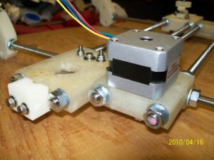
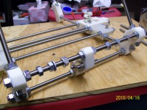
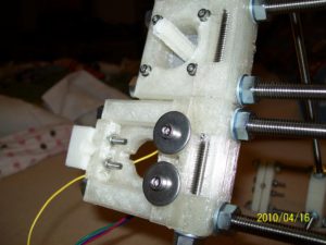
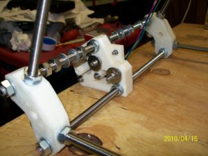
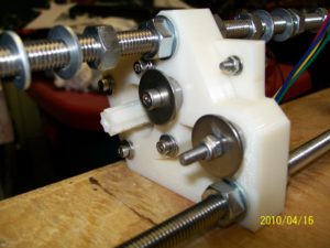
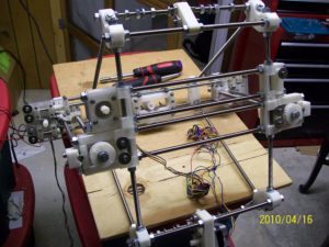
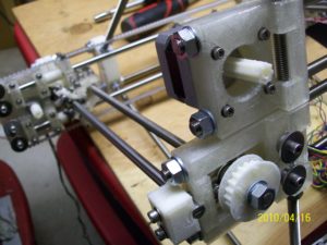
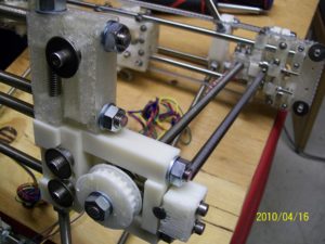
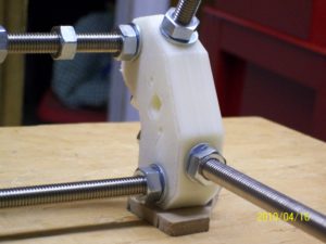
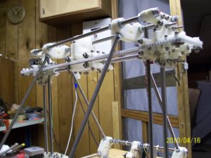
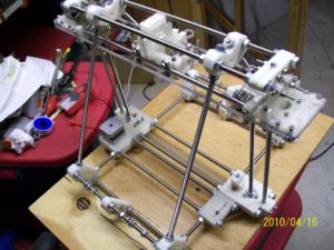
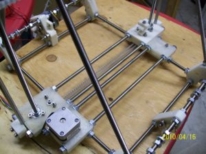
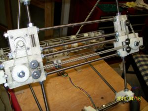
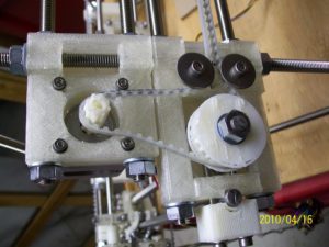
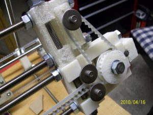
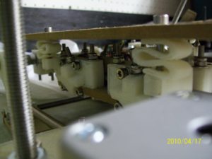
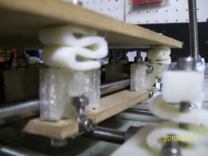
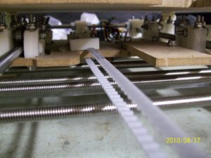
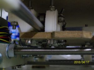
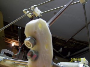
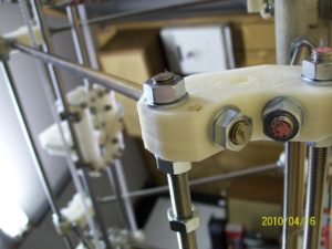
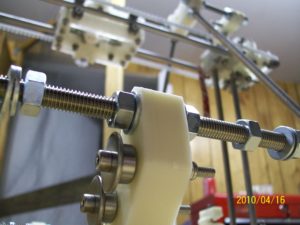
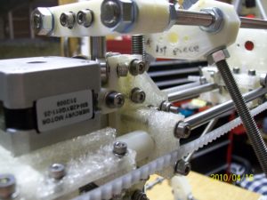
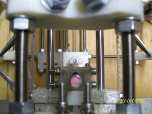
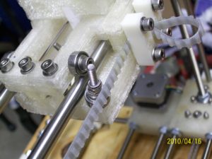
p.s. As a bonus, as if there weren’t enough pictures in this post, I figured I’d throw in seven almost-artistic shots since I’ve ended this post on such a down note. Enjoy.


Vincent Mulhall
I found a great…
Cheap Private Proxies
I found a great…
Mendy Shahbaz
I found a great…
Cecily Froehlich
I found a great…
Buy Proxies
I found a great…
Free Proxies Sites
I found a great…